


6
12
3
KEB COMBIVERT F5
Name: Basis
6
04.05.04
Section
Page
Date
©
KEB Antriebstechnik, 2002
All rights reserved
Chapter
Functional Description
Technology Control
%
Hz
cn.14
-
+
ru.52
cn.7
cn.8
v
t
cS.0
oP.0
cn.4 PID kp
cn.5 PID ki
cn.6 PID kd
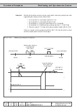
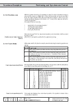
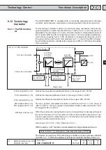
6.12.1 The PID Control-
ler
The KEB COMBIVERT is equipped with a universally programmable technology
controller, with it pressure, temperature or dancing position controls can be set up.
The technology controller consists of a set/actual value comparator, that puts the
system deviation on a PID controller. With cn.4, 5 and 6 the P-, I- and D component is
adjustable. The parameters cn.7 and cn.8 limit the maximum manipulated variable of
the controller. With the PID-controller fade-in time (cn.9) the controller amplification
can be driven up gently from 0...100%. Parameter cn.14 adjusts the frequency reach-
through ins Hz/%
(only F5-G/B)
.
Over parameter cn.11, 12 and 13 the PID-Controller,
the I-Controller and/or the controller fade-in can be reset. With cn.10 a PID-reset condition
can be adjusted.
6.12 Technology
Controller
Pic. 6.12.1 PID controller
Set value calculation
Actual value calculation
PID controller
cn.13 Fade in
reset / input
selection
cn.11 Reset PID /
input selection
cn.12 Reset I /
input selection
cn.10 PID Reset
condition
cn.9 PID
fading time
Digital inputs
PID controller KP (cn.4)
Defines the proportional amplification factor in the range of 0,00...250,00.
Defines the integral amplification factor in the range of 0,000...30,000.
Defines the differential amplification factor in the range 0,000...250,00.
PID controller KI (cn.5)
PID controller KD (cn.6)
PID positive limit (cn.7)
PID negative limit (cn.8)
The max. positive manipulated variable is determined with cn.7 in the range of
-400,0...400,0 %, the max. negative manipulated variable is determined with cn.8 in
the range of -400,0...400,0 %.
With it the control action during the start can be increased linear or decreased linear at
the reset of the fade-in. The time refers of 100% of the controller output value. If one
input is programmed for „Reset fade-in“ (cn.13) the fade-in is counted down at active
input and counted up at inactive input.
Value range: -0,01; 0,00 ... 300 s; Resolution: 0,01 s
With the setting „-0.01“ the fade-in is calculated according to following formula:
Fade-in factor = f_setting (ru.2) / max. setpoint value (o.P10/11)
The function is only active, if the technology controller is used as process controller
(cs.0 Bit 0...2 = 1). With the adjustment as setpoint controller the fade-in time is 0.
PID fade-in time (cn.9)