


6
11
KEB COMBIVERT F5-M / S
8
Name: Basis
06.05.04
Chapter
Section
Page
Date
©
KEB Antriebstechnik, 2002
All Rights reserved
Functional Desription
Positioning and Synchronous Control
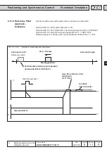
Reference switch input selection
(PS.18)
Start reference point approach
input selection (PS.19)
With PS.18 the input for the reference point switch is determined. It can also be
occupied together with a limit switch (see example 1). With PS.19 the input for
starting the reference point approach is defined.
With PS.17 an absolute position is adjusted in increments. After completing the
reference point approach this value is accpeted for the current position.
With PS.20 the acceleration and deceleration times of the reference point drive are
preset within the range of 0...300.00 s vorgegeben.
Reference point (PS.17)
With PS.21 the speed of the reference point drive is preset within the range of
±4000 min
-1
(dependent on ud.2). The driving free of the reference switch takes
place with only a quarter of the adjusted speed. The sign determines the preferred
direction.
Reference speed (PS.21)
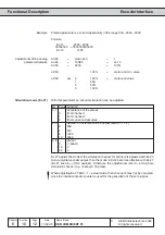
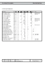
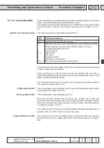
Bit -No. Decimal value Input
Terminal
0
1
ST (prog. input Ñcontrol release / resetì)
X2A.16
1
2
RST (prog. input Ñresetì)
X2A.17
2
4
F (prog. input Ñforwardì)
X2A.14
3
8
R (prog. input Ñreverseì)
X2A.15
4
16
I1 (prog. input 1)
X2A.10
5
32
I2 (prog. input 2)
X2A.11
6
64
I3 (prog. input 3)
X2A.12
7
128
I4 (prog. input 4)
X2A.13
8
256
IA (internal input A)
none
9
512
IB (internal input B)
none
10
1024
IC (internal input C)
none
11
2048
ID (internal input D)
none
Referenz acc/dec time (PS.20)
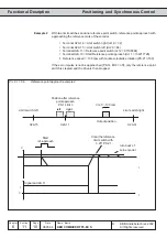
Limit switch left (PS.15)
Limit switch right (PS.16)
With these parameters the absolute limit positions to the right and the left are
adjusted. Prior to the start of a positioning it is checked whether the target lies
within the permissible range. The software limit switches work like Ñrealì limit
switches, i.e. the position is monitored in the speed-controlled operation and
synchronous mode. Only the selected direction of rotation is always evaluated.
The activation respectively the behavoiur takes place with parameter Pn.65 (response
software limit switch). The output function ÑReference point drive takes placeì is set
at valid actual position and
ï after completed reference point drive
ï after switch on, if PS.14 Bit 0...1 is = Ñ3ì
ï after manual setting of the reference position (PS.14 bit 6)
ï if PS.14 Bit 7 Ñcurrent position is validì is set
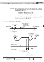
Hardware limit switch right
Hardware limit switch left
The inputs for the hardware limit switch are specified in the di-parameters (default
X2A.14 => F and X2A.15 => R). The hardware limit switches are activated with
Pn.7. If the hardware limit switches are activated but no input is defined, an error is
triggered upon selection of the direction of rotation. In order to give security against
cable breakage the limit switches are 0-active.
Only the selected direction of rotation is always evaluated. For this purpose it is
mandatory that the drive runs in the correct sense of rotation and that the limit
switches are not exchanged.