


7
6
3
7
KEB COMBIVERT F5
Name: Basis
28.01.03
6
Section
Page
Date
©
KEB Antriebstechnik, 2002
All rights reserved
Chapter
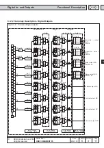
Functional Description
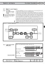
Digital In- and Outputs
t
t
t
t
t
1ms
t
t
t
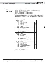
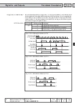
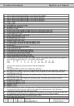
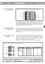
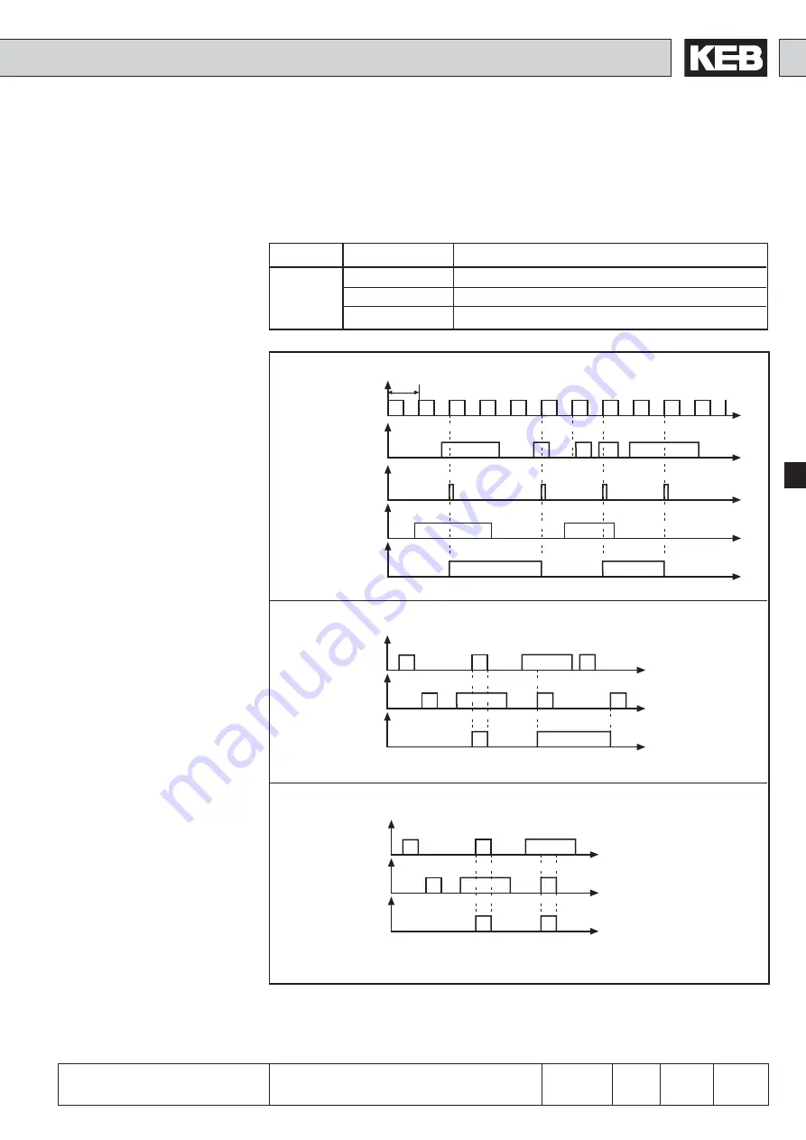
Edge-active or static Strobe?
As a standard the Strobe is edge-active, i.e. the input conditions on the Strobe input
are accepted with rising edge and maintained until the next edge. For some applications
it is sensible to use the Strobe in a manner of a gate function. In that case the Strobe
signal is static, i.e. the input signals are accepted for as long as the Strobe signal is
set (or for as long as the gate is open).
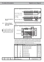
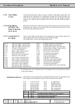
di.7 Strobe-mode
Fig. 6.3.8.a Edge-active Strobe (di.7=0)
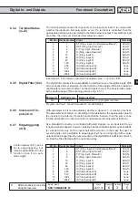
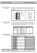
Fig. 6.3.8.b Static Strobe Mode 1 (di.7=1)
Signal at
terminals
Strobe input
Input status
Scanning grid
(acceptance upon
rising edge)
Strobe input
Resulting
Strobe signal
Signal at
terminals
Input status
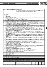
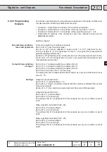
Parameter
Setting range
Function
di.7
0
edge-active Strobe (default)
1
static strobe - frooze if strobe is not active
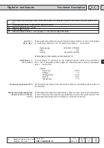
2
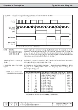
static strobe - only active at active strobe
t
t
t
Signal at
terminals
Strobe input
Input status
Fig. 6.3.8.c Static Strobe Mode 2 (di.7=2)