


6
1
KEB COMBIVERT F5-M / S
20
Name: Basis
12.05.04
Chapter
Section
Page
Date
©
KEB Antriebstechnik, 2002
All Rights reserved
Functional Desription
Operating and Unit Data
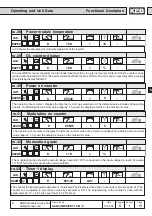
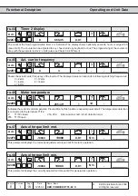
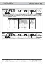
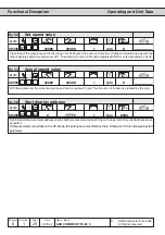
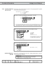
With do.51 the digital output signals can be assigned to the hardware outputs (see chapter 6.3). This parameter displays
the status of the output signals before the assignment according to following table. If several outputs are set, the total
sum of their decimal values is indicated.
Adr.
min
max
default
0250h
ru.80 digital output state
1
-
-
255
0
Bit -No.
Decimal value
Output
Terminal
0
1
O1 (Transistor output 1)
X2A.18
1
2
O2 (Transistor output 2)
X2A.19
2
4
R1 (Relay RLA,RLB,RLC)
X2A.24...26
3
8
R2 (Relay FLA,FLB,FLC)
X2A.27...29
4
16
OA (Internal output A)
keine
5
32
OB (Internal output B)
keine
6
64
OC (Internal output C)
keine
7
128
OD (Internal output D)
keine
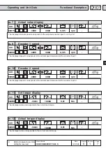
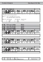
ru.81 displays the current active power of the inverter. In regenerative operation the negative values are displayed.
Adr.
min
max
default
0251h
ru.81
active power
0,01
kW
0,01
400,00
-400,00