


6
11
KEB COMBIVERT F5-M / S
4
Name: Basis
06.05.04
Chapter
Section
Page
Date
©
KEB Antriebstechnik, 2002
All Rights reserved
Functional Desription
Positioning and Synchronous Control
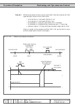
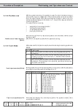
6.11.2 Slave Correction
Two parameters are available for the slave correction (angular displacment between
master and slave). The intented slave correction is adjusted in increments under
PS.4. The sign determines the direction of the correction. The actual correction can
then be triggered by a programmable input.
Setting of the slave correction in the range of -2147483648...2147483647 increments.
The correction is executed with the adjusted rampe times. During the slave correction
no changes are taken over into PS.4. The correction is completed if the internal counter
is equal PS.4.
With PS.3 and PS.10 the inputs are defined, with which the slave correction is started.
PS..3 starts the correction according to the direction of rotation specified with PS.4.
PS.10 inverts the direction of rotation.
Before the slave correction can be started, the synchronous control must be activated
(see PS.2).
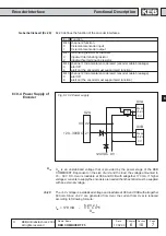
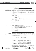
Shifting slave (PS.4)
Shifting slave input selection
(PS.3)
Shifting slave invers input
selection (PS.10)
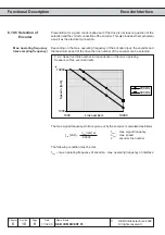
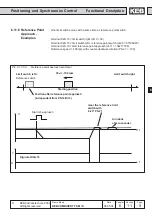
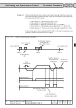
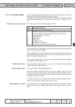
Start offset (PS.5)
On activating the synchronous run the slave tries to synchronize the master at the
torque limit. This leads in dependence on the position difference to overshootings.
With PS.5 a synchronization position can be preset in increments, which the master
must cover before it runs angular-synchronous with the slave. If on activating the
synchronous run master and slave speed are within the tolerance preset in LE.16, it is
directly switched into synchronous run. When starting from actual speed = 0 rpm the
slave covers half of the increments of the master (see PS.0 Bit 10).
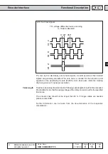
If synchronous is interrupted by limit switch, ST, error, the synchronizing always takes
place over the ramp times. Even if during synchronous operation the gear factor is
changed or the angular correction is started, the ramp time is active.
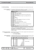
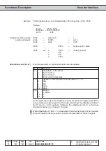
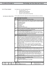
Bit -No. Decimal value
Input
Terminal
0
1
ST (prog. input Ñcontrol release / resetì)
X2A.16
1
2
RST (prog. input Ñresetì)
X2A.17
2
4
F (prog. input Ñforwardì)
X2A.14
3
8
R (prog. input Ñreverseì)
X2A.15
4
16
I1 (prog. input 1)
X2A.10
5
32
I2 (prog. input 2)
X2A.11
6
64
I3 (prog. input 3)
X2A.12
7
128
I4 (prog. input 4)
X2A.13
8
256
IA (internal input A)
none
9
512
IB (internal input B)
none
10
1024
IC (internal input C)
none
11
2048
ID (internal input D)
none
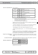
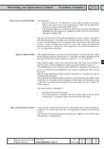
Master source (PS.1)
With PS.1 the encoder channel for master operation is determined.
PS.1 Channel
0
Encoder channel 1
1
Encoder channel 2 (default)
The source of actual value is determined with cS.1. If the master source is changed to
encoder channel 1, the source of actual value must be changed accordingly to channel
2.
cS.1 Channel
0
Encoder channel 1 (default)
1
Encoder channel 2
2
reserved for F5-G/B
Actual source (cS.1)