


3
6
3
3
KEB COMBIVERT F5
Name: Basis
28.01.03
6
Section
Page
Date
©
KEB Antriebstechnik, 2002
All rights reserved
Chapter
Functional Description
Digital In- and Outputs
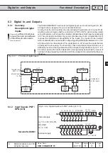
6.3.1
Summary
Description Digital
Inputs
6.3
Digital In- and Outputs
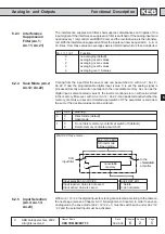
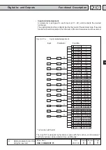
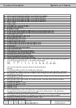
The KEB COMBIVERT has 8 external digital inputs and 4 internal inputs (IA...ID).
All inputs can be assigned to one or several functions.
Coming from the terminal strip it can be defined with parameter di.0 (not at F5-B),
whether external inputs shall be controlled in PNP or NPN (not at safety relais)
wiring. Parameter ru.21 shows the currently controlled input. Each input can optionally
(di.1) be set via terminal strip or by means of software with di.2. A digital filter (di.3)
reduces the interference susceptibility of the inputs. The inputs can be inverted
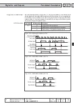
with di.4 and with di.5 one can switch to edge-triggering. With the parameters di. 6...di. 8
a Strobe-mode can be activated. The input status (ru.22) shows the inputs that are
actually set for processing. The function(s), that a programmed input carries out, is
defined by means of the input selection of the corresponding function or by di.11...22.
For safety reasons the control release (ST) must generally be switched by means of
hardware. Edge-triggering, inversion and strobe signal can be adjusted but have no
influence.
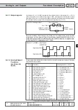
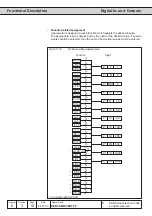
Fig. 6.3.1
Principle of digital inputs
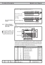
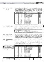
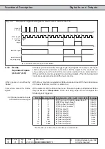
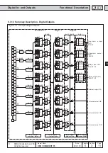
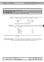
6.3.2
Input Signals PNP /
NPN (di.0)
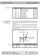
Fig. 6.3.2.a Digital inputs with PNP control (di.0 = 0)
U
in
= 18...26V DC ±0%
smoothed
R
i
= 2,1 k
Ω
8
di.0
di.2
di.1
di.3
di.4
1
di.5
12
12
di.8
di.7
di.6
12
1
ru.21
ru.22
12
4
PNP/
NPN
Terminal
status
Select
inputs
digital
Digital-
filter
Define
Strobe
input
Strobe
mode
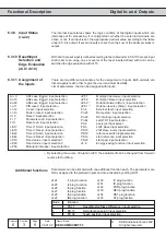
Input status
Assignment
of the inputs
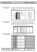
Terminal strip
X2A.10...17
Internal inputs
IA...ID
10 11 12 13 14 15
20
16 17
I1 I2 I3 I4
F
R
GND
ST RST
PE
X2A
22 23
24V
out
21
24V
in
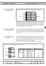
Internal supply
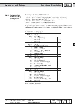
10 11 12 13 14 15
20
16 17
I1 I2 I3 I4
F
R
GND
ST RST
PE
X2A
22 23
24V
out
21
24V
in
+
External supply
24...30 VDC
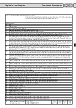
Observe the
different functional
range of the hard- and software
of the different control cards
(see chapter 3).
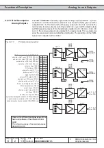
Not valid for BASIC!