


6
6
KEB COMBIVERT F5-M / S
12
Name: Basis
12.05.04
Chapter
Section
Page
Date
©
KEB Antriebstechnik, 2002
All Rights reserved
Functional Desription
Motor Data and Controller
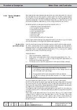
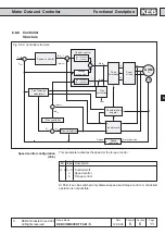
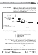
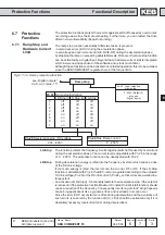
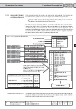
6.6.9 Current Control
(Torque Control)
The current control consists of two standard PI-controllers.
ï Active current controller (torque controller) with
speed-dependent precontrol
ï Magnetizing current controller
The basic setting of the controller is done automatically through the motor adaption
Fr.10 (see Chapter 6.6.3).
If in the individual case a fine adjustment should be necessary the proportional
gain factor can be adjusted with dS.0. The integral factor is adjusted with dS.1. The
values apply for the active current controller as well as for the magnetizing controller.
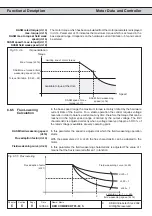
The precontrol of the active current controller can be changed with dr.21 at F5-M
and with dr.26 at F5-S.
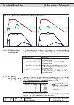
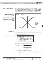
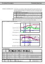
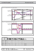
KP current (dS.0)
KI current (dS.1)
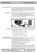
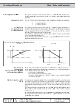
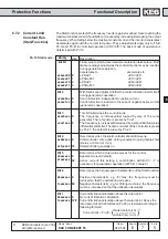
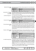
Restrictions for controlled
operation
The controlled operation is suited only as emergency operation for set-up or in
case of a faulty encoder.
Inverter operates according to adjusted current/frequency charancteristic (Chapt.
6.5).
Increased oscillating torque compared to controlled operation.
ru. 9 continues to indicate the actual speed measured by encoder 1.
Actual torque is internally set to zero, i.e. ru.12 always display the value 0. If
outputs are programmed to torque-dependent switching or if a torque signal is
given out over an analog output then the outputs behave like they do at actual
torque = 0.
dr.1 and dr.5 serve for the calculation of the pole pair number, for that reason they
must be adjusted correctly even in controlled operation.
All torque limits are without effect.
Speed and flux controller are not active.
No reference point run possible.
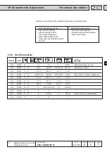
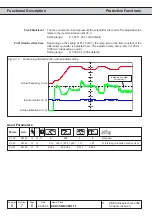
No load voltage (dr.21)
DSM - EMK voltage constant
(dr.26)