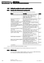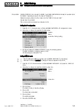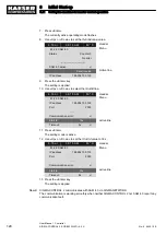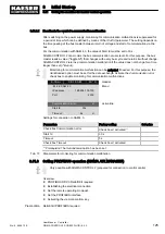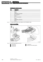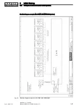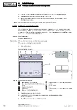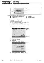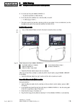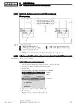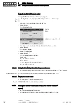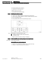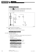
For connecting the machines to a network (LAN) or switch:
Connect the Ethernet cable for each machine to the LAN connection or switch.
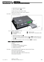
1. Attach the RJ45-plug to the cable end.
2. Plug the RJ45plug into the network socket until it latches.
8.11.4.2 Setting the controller of machine 1 as master
Precondition The electrical connection is made.
Access level 2 is activated.
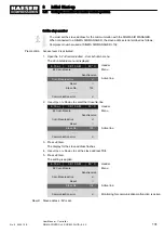
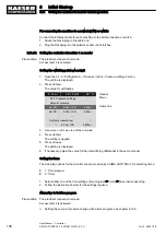
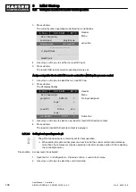
Setting the switching points pA and pB
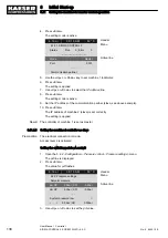
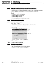
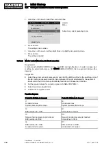
1. Open the 5.2.2
<Configuration – Pressure control – Pressure settings> menu.
The
pA line is displayed.
2. Press «Enter».
The value for
pA flashes.
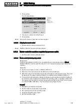
6 . 1 b a r
0 8 : 1 5 A M
8 0 ° C
Header
5.2.2 Pressure settings
Menu
Setpoint pressure
pA SP:
8.5bar ¦ SD:
−0.5bar
Active line
pB SP:
8.2bar ¦ SD:
−0.5bar
·········
System pressure low
☐
↓
<
5.0bar ¦ SD:
0.50bar
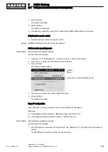
3. Use «Up» or «Down» to set the
pA value.
4. Press «Enter».
The setting is applied.
5. Press «Down».
The
pB line is displayed.
6. If necessary, adjust the value for the
pB switching differential in the same manner.
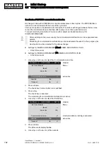
Setting the times
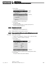
The following options for load control are are provided by SIGMA CONTROL 2 for selecting times:
■ 1: Time program
■ 2: Timer
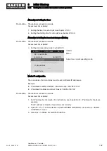
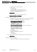
1. Select either one of the time settings (time program or timer) or base load sequencing.
2. Follow the instructions below for the settings required.
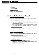
Alternative 1: Set time program
Precondition The electrical connection is made.
Access level 2 is activated.
➤ Setting the set-point pressure change with a time program; see chapter 8.10.2.
8
Initial Start-up
8.11 Setting the machine for master control operation
136
User Manual Controller
SIGMA CONTROL 2 SCREW FLUID ≥5.0.X
No.: 9_9450 12 E

