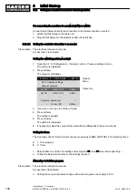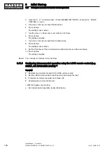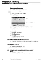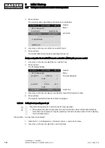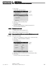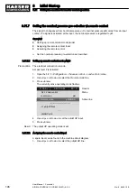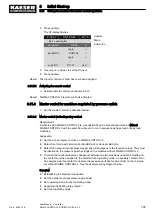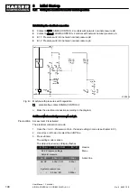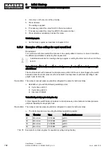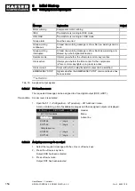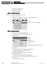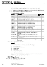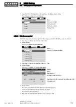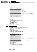
2. Use «Up» or «Down» to select the
Local mode line.
6 . 1 b a r
0 8 : 1 5 A M
8 0 ° C
Header
5.2.3 Load control
Menu
Local mode:
pA
Remote mode
: pA
Active line, current operating mode
------------------------------
▶1 pA/pB Clock
·········
pA/pB Cycle
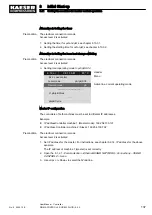
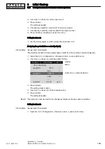
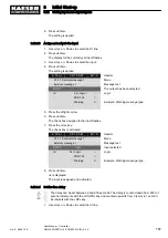
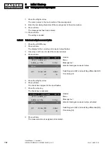
3. Press «Enter».
The setting mode is active.
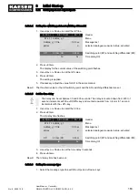
4. Use «Up» or «Down» to set the
pA/pB Clock or pA/pB Cycle operating mode.
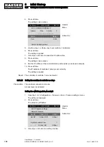
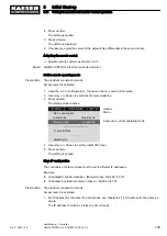
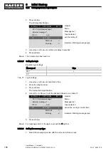
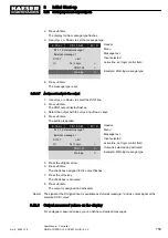
5. Press «Enter».
The setting is applied.
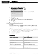
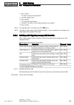
8.11.8.2 Master control without an electrical connection
Requirement:
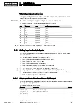
A machine with SIGMA CONTROL 2 (e. g. type BSD) and high flow rate is to work as a base load
machine. A second machine (e.g., SK) without SIGMA CONTROL 2 is to supply air in times of low
demand.
Suggestion:
■ Select the system set-point pressures pA and pB of the BSD machine for the switching point of
the SK machine's pressure switch to be in between. When pB is activated for the periods of
low demand, the SK machine automatically functions as the base load machine.
■ Set the required values for a clock program on SIGMA CONTROL 2.
■ Select local mode pA/pB Clock.
■ Activate the compressor timer
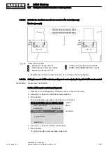
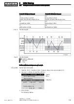
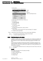
Function diagram:
Period t1–t7: high air demand
Period t8–t14: low air demand
t1
Air demand rises.
System pressure pNloc drops.
t8:
Air demand rises.
System pressure pNloc drops.
t2
BSD switches to LOAD.
t9:
SK switches to LOAD.
t3:
Network nominal pressure pA reached.
BSD switches to IDLE.
t10:
Network nominal pressure pB reached.
SK switches to IDLE.
t4:
BSD switches to LOAD.
Air demand not covered.
t11:
BSD switches to LOAD.
Air demand not covered.
8
Initial Start-up
8.11 Setting the machine for master control operation
150
User Manual Controller
SIGMA CONTROL 2 SCREW FLUID ≥5.0.X
No.: 9_9450 12 E

