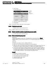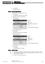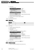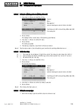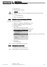
1. Open the 5.7.2
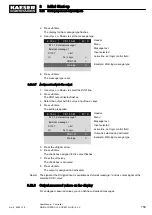
<Configuration – I/O periphery – Analogue values> menu.
The
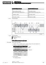
Analogue values menu is displayed
6 . 1 b a r 0 8 : 1 5 A M 8 0 ° C
5.7.2 Analogue values
Menu
▶1 AnMod
Analogue modules
▶2 AI
Analogue inputs
▶3 AO
Analogue outputs
▶4 PD
Process Data
8.12.3.2 Enter the message text
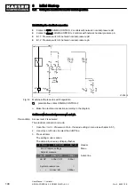
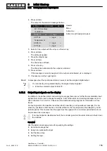
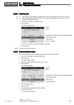
In the following example, a message from the analogue module is defined by pressure value p1.
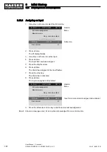
1. Use «Up» or «Down» to select the
AnMod line.
2. Press «Enter».
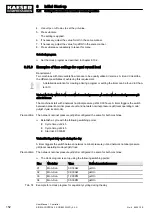
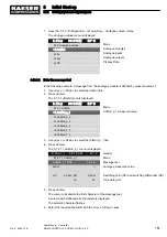
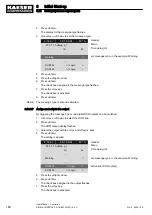
The 5.7.2.1
AnMod menu is displayed.
6 . 1 b a r 0 8 : 1 5 A M 8 0 ° C
5.7.2.1 AnMod
Menu
▶1 AnMod_p_1
AnMod_p_1 measured value
▶2 AnMod_p_2
▶3 AnMod_p_3
▶4 AnMod_p_4
▶5 AnMod_T_1
▶6 AnMod_T_2
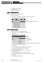
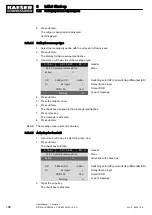
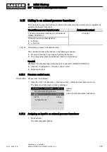
3. Use «Up» or «Down» to select the
AnMod_p_1 line.
4. Press «Enter».
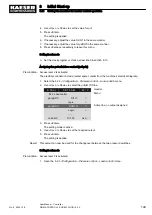
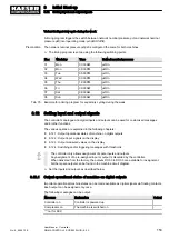
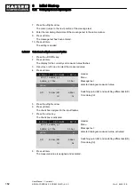
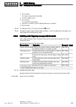
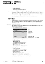
The 5.7.2.1.1 AnMod_p_1 menu is displayed.
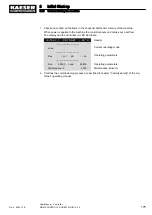
6 . 1 b a r
0 8 : 1 5 A M
8 0 ° C
Header
5.7.2.1.1 AnMod_p_1
Menu
AnMod_p_1 Title
0.0 bar
Message text
pNloc
☐
analogue measured value
·········
SP:
8.0bar ¦ SD:
−0.5bar
Switching point (SP) and switching differential (SD)
td:
0s
Time delay (td)
·········
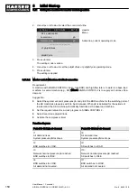
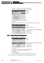
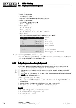
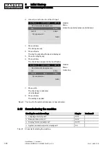
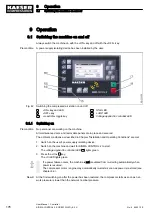
5. Press «Enter».
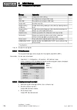
The cursor is located at the first character of the message text.
A column with alphanumeric characters is displayed.
The selected character flashes.
6. Select the required character with the «Up» or «Down» keys.
8
Initial Start-up
8.12 Setting input and output signals
No.: 9_9450 12 E
User Manual Controller
SIGMA CONTROL 2 SCREW FLUID ≥5.0.X
161

