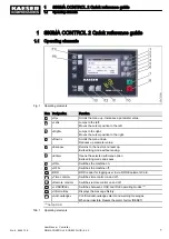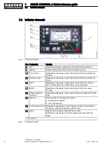
Tab. 1 Operating elements ....................................................................................................................
1
Tab. 2 Indicator elements ......................................................................................................................
2
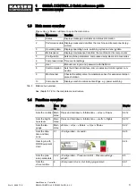
Tab. 3 Main menu overview ..................................................................................................................
3
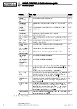
Tab. 4 Functions overview .....................................................................................................................
3
Tab. 5 Danger levels and their definition (personal injury) ....................................................................
8
Tab. 6 Danger levels and their definition (damage to property) ............................................................
8
Tab. 7 Formatting options ......................................................................................................................
9
Tab. 8 Versions and Options .................................................................................................................
10
Tab. 9 User interface .............................................................................................................................
10
Tab. 10 Display data ................................................................................................................................
11
Tab. 11 MCS interfaces ...........................................................................................................................
11
Tab. 12 MCSIO interfaces .......................................................................................................................
12
Tab. 13 RFID ...........................................................................................................................................
12
Tab. 14 Number of internal inputs and outputs .......................................................................................
13
Tab. 15 Cable lengths .............................................................................................................................
13
Tab. 16 SC2IOM-1 ..................................................................................................................................
14
Tab. 17 SC2IOM-2 ..................................................................................................................................
14
Tab. 18 SC2IOM-3 ..................................................................................................................................
14
Tab. 19 Power supply specifications .......................................................................................................
15
Tab. 20 Cable lengths .............................................................................................................................
15
Tab. 21 Degree of protection, IOM ..........................................................................................................
15
Tab. 22 IOM dimensions .........................................................................................................................
15
Tab. 23 Pressure transducer ...................................................................................................................
15
Tab. 24 Resistance thermometer ............................................................................................................
16
Tab. 25 Modem i.Box − versions and options .........................................................................................
16
Tab. 26 Technical data KAESER i.Box ...................................................................................................
17
Tab. 27 Operating elements ....................................................................................................................
22
Tab. 28 Display elements ........................................................................................................................
23
Tab. 29 RFID reader ................................................................................................................................
24
Tab. 30 Data in the header depending on the machine type ...................................................................
25
Tab. 31 Reset check box status ..............................................................................................................
27
Tab. 32 Check box status ........................................................................................................................
27
Tab. 33 KAESER CONNECT functions ...................................................................................................
28
Tab. 34 Menu structure of main menu .....................................................................................................
31
Tab. 35
Status menu ...............................................................................................................................
35
Tab. 36
Configuration menu ....................................................................................................................
37
Tab. 37
Pressure control menu ...............................................................................................................
40
Tab. 38
I/O periphery menu ..................................................................................................................... 42
Tab. 39
Communication menu ................................................................................................................
45
Tab. 40
Connections menu .....................................................................................................................
46
Tab. 41
Components menu .....................................................................................................................
47
Tab. 42
Power switching menu ...............................................................................................................
48
Tab. 43 Machine identification .................................................................................................................
55
Tab. 44 Remote control identification ......................................................................................................
55
Tab. 45 Machine identification .................................................................................................................
55
Tab. 46 Supported languages .................................................................................................................
58
Tab. 47 Date formats ...............................................................................................................................
66
Tab. 48 Possible settings for the time format ..........................................................................................
67
Tab. 49 Possible settings for the pressure unit .......................................................................................
68
Tab. 50 Possible settings for the temperature unit ..................................................................................
69
Tab. 51 Display illumination .....................................................................................................................
69
Tab. 52 Network parameters ...................................................................................................................
72
Tab. 53 E-mail parameters ......................................................................................................................
74
Tab. 54 Control key functions ..................................................................................................................
80
List of Tables
No.: 9_9450 12 E
User Manual Controller
SIGMA CONTROL 2 SCREW FLUID ≥5.0.X
vii


