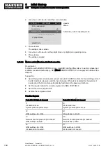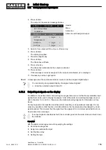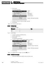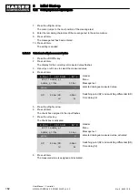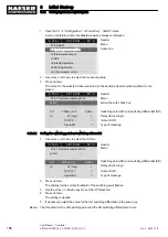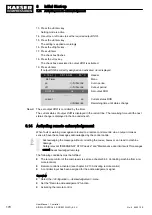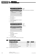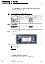
2. Press «Enter».
The display for the message type flashes.
3. Use «Up» or «Down» to set the message type.
6 . 1 b a r
0 8 : 1 5 A M
8 0 ° C
Header
5.7.2.1.1 AnMod_p_1
Menu
td:
0s
Time delay (td)
·········
Warning
☐
set message type, in the example: Warning
·········
DOR1.02
☐ ¦ Logic:
+
DOR1.03
☐ ¦ Logic:
+
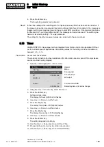
4. Press «Enter».
5. Press the «Right» arrow.
6. Press «Enter».
The check box assigned to the message type flashes.
7. Press the «Up» key.
The check box is activated.
8. Press «Enter».
Result The message type is set and activated.
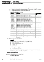
8.12.3.7 Assign and activate the output
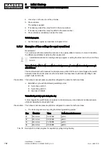
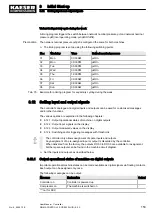
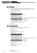
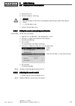
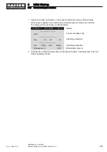
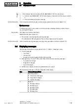
By triggering the message one or two digital DOR outputs can be switched.
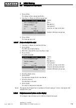
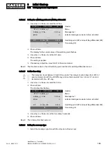
1. Use «Up» or «Down» to select the
DOR line.
2. Press «Enter».
The
DOR output display flashes.
3. Select the output with the «Up» and «Down» keys.
4. Press «Enter».
The setting is applied.
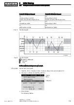
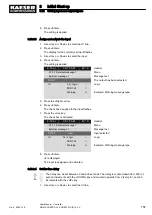
6 . 1 b a r
0 8 : 1 5 A M
8 0 ° C
Header
5.7.2.1.1 AnMod_p_1
Menu
td:
0s
Time delay (td)
·········
Warning
☐
set message type, in the example: Warning
·········
DOR1.02
☐ ¦ Logic:
+
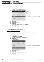
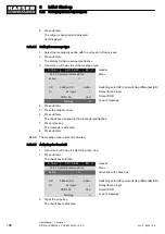
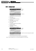
active line (DOR output)
DOR1.03
☐ ¦ Logic:
+
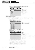
5. Press the «Right» arrow.
6. Press «Enter».
The check box assigned to the output flashes.
7. Press the «Up» key.
The check box is activated.
8
Initial Start-up
8.12 Setting input and output signals
164
User Manual Controller
SIGMA CONTROL 2 SCREW FLUID ≥5.0.X
No.: 9_9450 12 E

