System Overview
J4350 Power System
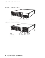
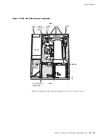
The J4350 Services Router uses either AC or DC power. The autosensing power
supply (see Figure 2 or Figure 4) distributes the different output voltages to
the router components according to their voltage requirements.
The power supply is fixed in the chassis, and is not field-replaceable. The AC power
supply has a single AC appliance inlet that requires a dedicated AC power feed. The
DC power supply has a terminal block that provides a single DC input (–48 VDC
and return) and requires a dedicated 15 A (–48 VDC) circuit breaker.
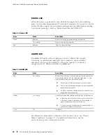
The J4350 AC-powered chassis has a power switch and does not include a power LED.
The J4350 DC-powered chassis includes a power supply LED located to the upper
right of the power supply connector. Table 11 describes the power supply LED.
Table 11: Power Supply LED
State
Description
Off
No power is flowing to the power supply.
Green
Power supply is connected and power is flowing.
Yellow
Power supply is connected, but the router is not powered on.
For information about site power preparations, see “Power Guidelines,
Requirements, and Specifications” on page 74. For information about connecting
the router to power and ground, see “Connecting Power” on page 86.
J6350 Power System
The J6350 Services Router uses either AC or DC power. You can install one or two
autosensing, load-sharing power supplies at the bottom rear of the chassis, as shown
in Figure 3 or Figure 5. The power supplies distribute the different output voltages to
the router components, depending on their voltage requirements. When two power
supplies are installed and operational, they automatically share the electrical load.
For full redundancy, two power supplies are required. If a power supply stops
functioning for any reason, the second power supply instantly begins providing
all the power the router needs for normal functioning. It can provide full power
indefinitely. Power supplies on the J6350 Services Router can be hot-swapped.
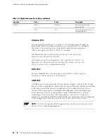
Each power supply has an LED located to the upper right of the power supply
connector. Table 11 describes the power supply LED.
For information about site power preparations, see “Power Guidelines,
Requirements, and Specifications” on page 74. For information about connecting
the router to power and ground, see “Connecting Power” on page 86.
Power supplies on J6350 Services Routers are hot-removable and hot-insertable.
You can remove and replace a redundant power supply without powering down the
J4350 and J6350 Services Router Hardware Features
21
Содержание J4350
Страница 14: ...J4350 and J6350 Services Router Getting Started Guide xiv Table of Contents...
Страница 22: ...2 J series Overview...
Страница 68: ...J4350 and J6350 Services Router Getting Started Guide 48 Field Replaceable PIMs...
Страница 75: ...Services Router User Interface Overview Figure 25 J Web Layout Using the J Web Interface 55...
Страница 88: ...J4350 and J6350 Services Router Getting Started Guide 68 Using the Command Line Interface...
Страница 90: ...70 Installing a Services Router...
Страница 100: ...J4350 and J6350 Services Router Getting Started Guide 80 Site Preparation Checklist...
Страница 112: ...J4350 and J6350 Services Router Getting Started Guide 92 Powering a Services Router On and Off...
Страница 144: ...J4350 and J6350 Services Router Getting Started Guide 124 Verifying Secure Web Access...
Страница 160: ...J4350 and J6350 Services Router Getting Started Guide 140 Verifying J series License Management...
Страница 162: ...142 Maintaining Services Router Hardware...
Страница 194: ...J4350 and J6350 Services Router Getting Started Guide 174 Troubleshooting Hardware Components...
Страница 202: ...J4350 and J6350 Services Router Getting Started Guide 182 Packing a Router or Component for Shipment...
Страница 204: ...184 J series Requirements and Specifications...
Страница 220: ...J4350 and J6350 Services Router Getting Started Guide 200 ISDN RJ 45 Connector Pinout...
Страница 267: ...Part 5 Index Index 247...
Страница 268: ...248 Index...

