303
Device Comparison
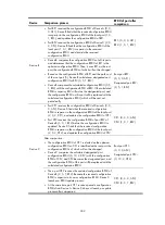
process
BPDU of port after
comparison
After comparison:
•
Because the root path cost of CP2 (9) (root path cost of the
BPDU (5) plus path cost corresponding to CP2 (4)) is smaller
than the root path cost of CP1 (10) (root path cost of the
BPDU (0) + path cost corresponding to CP2 (10)), the BPDU
of CP2 is elected as the optimum BPDU, and CP2 is elected
as the root port, the messages of which will not be changed.
•
After comparison between the configuration BPDU of CP1
and the calculated designated port configuration BPDU,
port CP1 is blocked, with the configuration BPDU of the port
unchanged, and the port will not receive data from Device A
until a spanning tree calculation process is triggered by a
new event, for example, the link from Device B to Device C
going down.
Blocked port CP2:
{0, 0, 0, AP2}
Root port CP2:
{0, 5, 1, BP2}
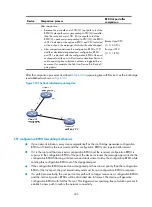
After the comparison processes described in
, a spanning tree with Device A as the root bridge
is established as shown in
.
Figure 313
The final calculated spanning tree
STP configuration BPDU forwarding mechanism
•
Upon network initiation, every device regards itself as the root bridge, generates configuration
BPDUs with itself as the root, and sends the configuration BPDUs at a regular hello interval.
•
If it is the root port that received a configuration BPDU and the received configuration BPDU is
superior to the configuration BPDU of the port, the device increases the message age carried in the
configuration BPDU following a certain rule and starts a timer to time the configuration BPDU while
sending this configuration BPDU out of the designated port.
•
If the configuration BPDU received on a designated port has a lower priority than the configuration
BPDU of the local port, the port immediately sends out its own configuration BPDU in response.
•
If a path becomes faulty, the root port on this path will no longer receive new configuration BPDUs
and the old configuration BPDUs will be discarded due to timeout. The device will generate
configuration BPDUs with itself as the root. This triggers a new spanning tree calculation process to
establish a new path to restore the network connectivity.
Содержание MSR SERIES
Страница 17: ...xv Documents 835 Websites 835 Conventions 836 Index 838 ...
Страница 20: ...3 Figure 3 Initial page of the Web interface ...
Страница 42: ...25 Figure 13 Firefox Web browser setting ...
Страница 59: ...42 Figure 27 Checking the basic service configuration ...
Страница 73: ...56 Figure 35 Sample interface statistics ...
Страница 156: ...139 Figure 139 Rebooting the 3G modem ...
Страница 168: ...151 Figure 152 Configuring Web server 2 ...
Страница 174: ...157 Figure 158 Configure the URL filtering function ...
Страница 187: ...170 Upon detecting the Land or Smurf attack on Ethernet 0 2 Router outputs an alarm log and drops the attack packet ...
Страница 242: ...225 Figure 233 Enabling the DHCP client on interface Ethernet 0 1 ...
Страница 247: ...230 Figure 236 The page for configuring an advanced IPv4 ACL ...
Страница 255: ...238 Figure 241 Advanced limit setting ...
Страница 298: ...281 e Click Apply 2 Configure Router B in the same way Router A is configured ...
Страница 354: ...337 Figure 339 Configuring a login control rule so Host B cannot access Router through the Web ...
Страница 400: ...383 Figure 387 Verifying the configuration ...
Страница 405: ...388 ...
Страница 523: ...506 Figure 530 Ping configuration page ...
Страница 538: ...521 a Click Device A on the topology diagram b Click Ethernet 0 2 on the panel diagram c Click Port Guard ...
Страница 744: ...727 Verifying the configuration In the case that the IP network is unavailable calls can be made over PSTN ...
Страница 775: ...758 Figure 785 Configuring a jump node ...
Страница 791: ...774 Figure 801 Configuring a jump node ...


