691
Item Description
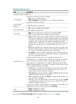
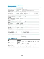
ISDN Protocol Type
Set the ISDN protocol to be run on an ISDN interface: DSS1, QSIG, or ETSI.
By default, an ISDN interface runs DSS1.
ISDN Working Mode
Set the ISDN working mode: network side mode or user side mode.
By default, an ISDN interface operates in user side mode.
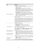
ISDN Timeslot Management
Configure local ISDN B channel management.
•
Disable
—Local ISDN B channel management is disabled and is in the
charge of ISDN switch.
•
Common management
—Device operates in local B channel management
mode to select available B channels for calls. However, the ISDN switch
still has a higher priority in B channel selection. If a locally selected B
channel is different from that selected by the ISDN switch, the one
indicated by the ISDN switch is used for communication.
•
Forced management
—Device operates in forced local B channel
management mode. In this mode, the device indicates in the Channel ID
information element of a call Setup message that the local B channel is
mandatory and unchangeable. If the ISDN switch indicates a B channel
different from the local one, the call fails.
By default, the local ISDN B channel management is not enabled and is in the
charge of ISDN switch.
It is very important to put appropriate control on the B channels used for calls
in process, especially in PRI mode. Proper channel management can improve
call efficiency and reduce call loss.
Typically, the centralized B channel management provided by exchanges
can work well. For this reason, you should adopt the management function
provided by exchanges in most cases, despite that the ISDN module can
provide the channel management function as well.
ISDN Timeslot Order
Set a B channel selection method:
•
Ascending order
—Select B channels in ascending order.
•
Descending order
—Select B channels in descending order.
When operating in B channel local management mode, the device selects B
channels in ascending order by default.
When the exchange manages B channels, these options take no effect. If you
select the
Disable
option in the
ISDN Timeslot Management
area, these
options take no effect.
ISDN Overlap-Sending
•
Enable
—Set the ISDN interface to send the called number in overlap
mode. In this mode, the digits of each called number are sent separately
and the maximum number of the digits sent each time can be set.
•
Disable
—Set the ISDN interface to send the called number in full-sending
mode. In this mode, all the digits of each called number are collected and
sent at a time.
By default, the ISDN interface sends the called number in full-sending mode.
Max Number of Digits that
Can Be Sent Each Time
Progress-to-Alerting
Conversion
•
Enable
—Enable the ISDN interface to convert received Progress messages
into Alerting messages.
•
Disable
—Disable the progress-to-alerting conversion function.
This option just takes effects on messages received on an ISDN interface.
Содержание MSR SERIES
Страница 17: ...xv Documents 835 Websites 835 Conventions 836 Index 838 ...
Страница 20: ...3 Figure 3 Initial page of the Web interface ...
Страница 42: ...25 Figure 13 Firefox Web browser setting ...
Страница 59: ...42 Figure 27 Checking the basic service configuration ...
Страница 73: ...56 Figure 35 Sample interface statistics ...
Страница 156: ...139 Figure 139 Rebooting the 3G modem ...
Страница 168: ...151 Figure 152 Configuring Web server 2 ...
Страница 174: ...157 Figure 158 Configure the URL filtering function ...
Страница 187: ...170 Upon detecting the Land or Smurf attack on Ethernet 0 2 Router outputs an alarm log and drops the attack packet ...
Страница 242: ...225 Figure 233 Enabling the DHCP client on interface Ethernet 0 1 ...
Страница 247: ...230 Figure 236 The page for configuring an advanced IPv4 ACL ...
Страница 255: ...238 Figure 241 Advanced limit setting ...
Страница 298: ...281 e Click Apply 2 Configure Router B in the same way Router A is configured ...
Страница 354: ...337 Figure 339 Configuring a login control rule so Host B cannot access Router through the Web ...
Страница 400: ...383 Figure 387 Verifying the configuration ...
Страница 405: ...388 ...
Страница 523: ...506 Figure 530 Ping configuration page ...
Страница 538: ...521 a Click Device A on the topology diagram b Click Ethernet 0 2 on the panel diagram c Click Port Guard ...
Страница 744: ...727 Verifying the configuration In the case that the IP network is unavailable calls can be made over PSTN ...
Страница 775: ...758 Figure 785 Configuring a jump node ...
Страница 791: ...774 Figure 801 Configuring a jump node ...


