87
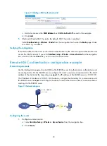
Figure 61
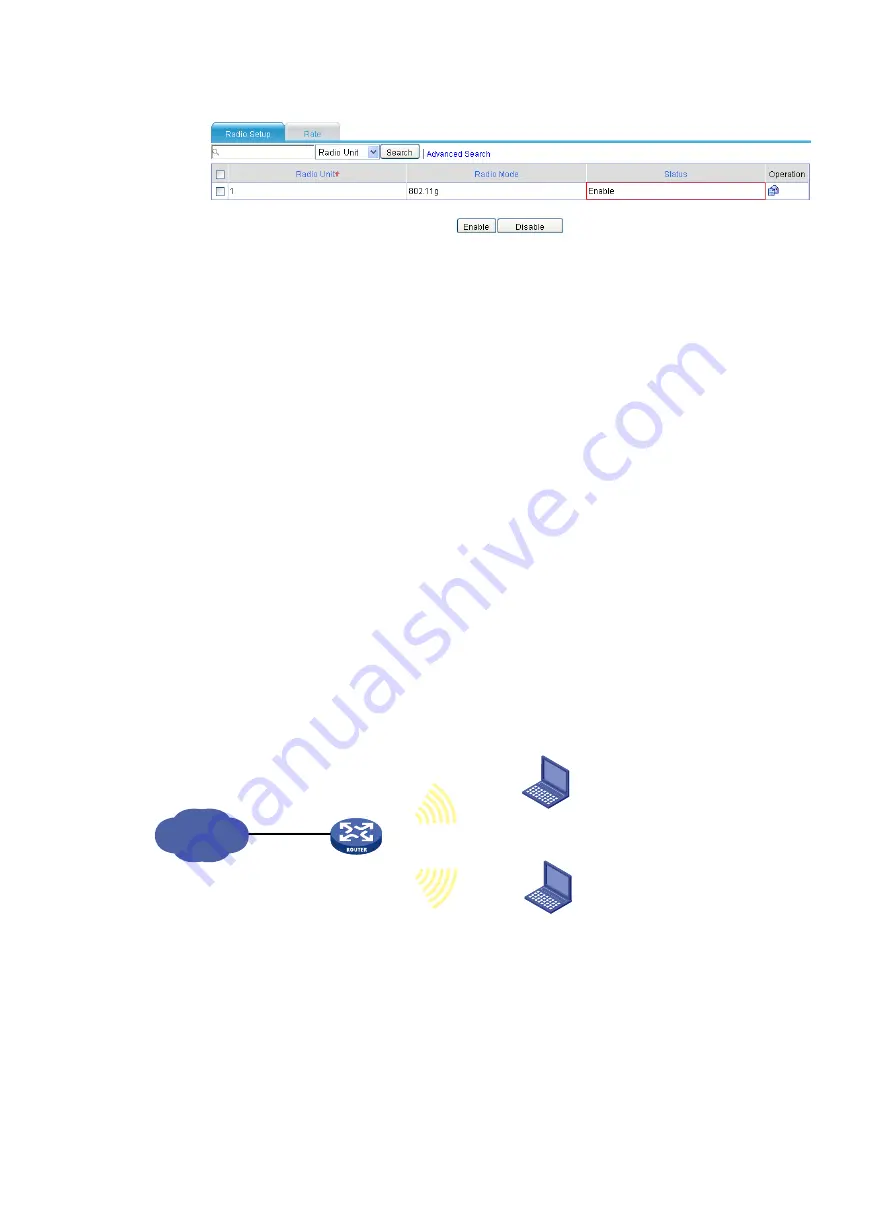
Enabling 802.11g radio
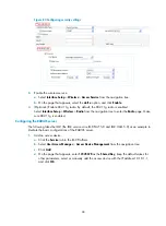
Verifying the configuration
If you select
Interface Setup
>
Wireless
>
Summary
from the navigation tree, and click the
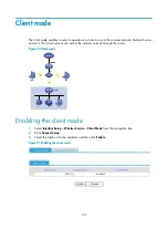
Client
tab, you
can view the online clients.
Configuration guidelines
Follow these guidelines when you configure a wireless service:
•
Select a correct district code.
•
Make sure the radio unit is enabled.
Access service-based VLAN configuration example
Network requirements
An AP can provide multiple wireless access services. Different wireless access services can use different
wireless security policies, and can be bound to different VLANs to implement wireless access user
isolation.
As shown in
, configure wireless VLANs to satisfy the following requirements:
•
Set up a wireless access service named
research
, and configure it to use the PSK authentication.
Clients that access the wireless network are in VLAN 2.
•
Set up a wireless access service named
office
, and configure it to use the clear text authentication.
Clients that access the wireless network are in VLAN 3.
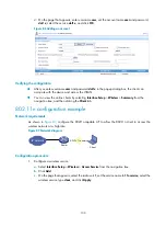
Figure 62
Network diagram
Configuration procedure
1.
Configure a wireless service named
research
.
a.
Select
Interface Setup
>
Wireless
>
Access Service
from the navigation tree.
b.
Click
Create
.
c.
Configure the name of the wireless service as
research
, and select the wireless service type
crypto
.
IP network
Client
:
0014-6c8a-43ff
SSID
:
research
SSID
:
office
Client
:
0040-96b3-8a77
VLAN
:
2
VLAN
:
3
Router
Содержание MSR SERIES
Страница 17: ...xv Documents 835 Websites 835 Conventions 836 Index 838 ...
Страница 20: ...3 Figure 3 Initial page of the Web interface ...
Страница 42: ...25 Figure 13 Firefox Web browser setting ...
Страница 59: ...42 Figure 27 Checking the basic service configuration ...
Страница 73: ...56 Figure 35 Sample interface statistics ...
Страница 156: ...139 Figure 139 Rebooting the 3G modem ...
Страница 168: ...151 Figure 152 Configuring Web server 2 ...
Страница 174: ...157 Figure 158 Configure the URL filtering function ...
Страница 187: ...170 Upon detecting the Land or Smurf attack on Ethernet 0 2 Router outputs an alarm log and drops the attack packet ...
Страница 242: ...225 Figure 233 Enabling the DHCP client on interface Ethernet 0 1 ...
Страница 247: ...230 Figure 236 The page for configuring an advanced IPv4 ACL ...
Страница 255: ...238 Figure 241 Advanced limit setting ...
Страница 298: ...281 e Click Apply 2 Configure Router B in the same way Router A is configured ...
Страница 354: ...337 Figure 339 Configuring a login control rule so Host B cannot access Router through the Web ...
Страница 400: ...383 Figure 387 Verifying the configuration ...
Страница 405: ...388 ...
Страница 523: ...506 Figure 530 Ping configuration page ...
Страница 538: ...521 a Click Device A on the topology diagram b Click Ethernet 0 2 on the panel diagram c Click Port Guard ...
Страница 744: ...727 Verifying the configuration In the case that the IP network is unavailable calls can be made over PSTN ...
Страница 775: ...758 Figure 785 Configuring a jump node ...
Страница 791: ...774 Figure 801 Configuring a jump node ...


