467
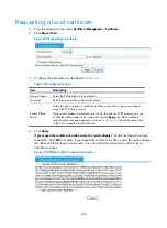
Figure 494
Retrieving the CRL
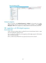
Verifying the configuration
After the configuration, select
Certificate Management
>
Certificate
from the navigation tree to display
detailed information about the retrieved CA certificate and local certificate, or select
Certificate
Management
>
CRL
from the navigation tree to display detailed information about the retrieved CRL.
IKE negotiation with RSA digital signature
Network requirements
An IPsec tunnel is set up between Router A and Router B to secure the traffic between Host A on subnet
10.1.1.0/24 and Host B on subnet 11.1.1.0/24.
Router A and Router B use IKE for IPsec tunnel negotiation and RSA digital signature of a PKI certificate
system for identity authentication.
Router A and Router B use different CAs. They might also use the same CA as required.
Содержание MSR SERIES
Страница 17: ...xv Documents 835 Websites 835 Conventions 836 Index 838 ...
Страница 20: ...3 Figure 3 Initial page of the Web interface ...
Страница 42: ...25 Figure 13 Firefox Web browser setting ...
Страница 59: ...42 Figure 27 Checking the basic service configuration ...
Страница 73: ...56 Figure 35 Sample interface statistics ...
Страница 156: ...139 Figure 139 Rebooting the 3G modem ...
Страница 168: ...151 Figure 152 Configuring Web server 2 ...
Страница 174: ...157 Figure 158 Configure the URL filtering function ...
Страница 187: ...170 Upon detecting the Land or Smurf attack on Ethernet 0 2 Router outputs an alarm log and drops the attack packet ...
Страница 242: ...225 Figure 233 Enabling the DHCP client on interface Ethernet 0 1 ...
Страница 247: ...230 Figure 236 The page for configuring an advanced IPv4 ACL ...
Страница 255: ...238 Figure 241 Advanced limit setting ...
Страница 298: ...281 e Click Apply 2 Configure Router B in the same way Router A is configured ...
Страница 354: ...337 Figure 339 Configuring a login control rule so Host B cannot access Router through the Web ...
Страница 400: ...383 Figure 387 Verifying the configuration ...
Страница 405: ...388 ...
Страница 523: ...506 Figure 530 Ping configuration page ...
Страница 538: ...521 a Click Device A on the topology diagram b Click Ethernet 0 2 on the panel diagram c Click Port Guard ...
Страница 744: ...727 Verifying the configuration In the case that the IP network is unavailable calls can be made over PSTN ...
Страница 775: ...758 Figure 785 Configuring a jump node ...
Страница 791: ...774 Figure 801 Configuring a jump node ...


