431
SSL VPN configuration example
Network requirements
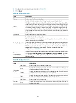
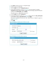
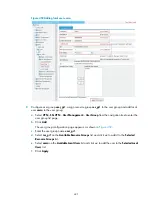
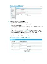
As shown in
, request a certificate and enable SSL VPN service on the SSL VPN gateway so
that users can use HTTPS to log in to the SSL VPN gateway to access the internal resources of the
corporate network.
In this configuration example:
•
In this example, the CA runs the Windows Server and the SCEP plugin is required on the CA.
•
The IP address of the SSL VPN gateway is 10.1.1.1/24. The IP address of the CA is 10.2.1.1/24, and
the name of the CA is CA server. The CA is used to issue certificates to the SSL VPN gateway and
remote users.
•
Perform RADIUS authentication for SSL VPN users. The IP address of the RADIUS server (a IMC
server) is 10.153.10.131/24. After passing authentication, an SSL VPN user can access the internal
technology website whose IP address is 10.153.1.223, all hosts on subnet 10.153.2.0/24, and the
security sever whose IP address is 10.153.2.25 through the FTP shortcut.
•
Configure a public account named
usera
. Specify that only one user can use the public account to
log in at a time. Configure local authentication for the public account and authorize a user who logs
in by using the public account to access the shared desktop provided by internal host
10.153.70.120.
•
Specify the default authentication method as RADIUS for the SSL VPN domain and enable
verification code authentication.
Figure 442
Network diagram
Configuration prerequisites
•
The SSL VPN gateway, the CA, and the hosts used by remote users can reach each other.
•
The CA is enabled with the CA service and can issue certificates to the SSL VPN gateway and the
hosts.
•
The RADIUS server is correctly configured to provide normal authentication function for users. In this
example, you need to configure the shared key as
expert
, configure the user account and user
group information, and add users to user group
user_gr2
.
Device
SSL VPN gateway
Host
Remote user
Internal servers
CA
Internet
10.2.1.1/24
10.1.1.1/24
Содержание MSR SERIES
Страница 17: ...xv Documents 835 Websites 835 Conventions 836 Index 838 ...
Страница 20: ...3 Figure 3 Initial page of the Web interface ...
Страница 42: ...25 Figure 13 Firefox Web browser setting ...
Страница 59: ...42 Figure 27 Checking the basic service configuration ...
Страница 73: ...56 Figure 35 Sample interface statistics ...
Страница 156: ...139 Figure 139 Rebooting the 3G modem ...
Страница 168: ...151 Figure 152 Configuring Web server 2 ...
Страница 174: ...157 Figure 158 Configure the URL filtering function ...
Страница 187: ...170 Upon detecting the Land or Smurf attack on Ethernet 0 2 Router outputs an alarm log and drops the attack packet ...
Страница 242: ...225 Figure 233 Enabling the DHCP client on interface Ethernet 0 1 ...
Страница 247: ...230 Figure 236 The page for configuring an advanced IPv4 ACL ...
Страница 255: ...238 Figure 241 Advanced limit setting ...
Страница 298: ...281 e Click Apply 2 Configure Router B in the same way Router A is configured ...
Страница 354: ...337 Figure 339 Configuring a login control rule so Host B cannot access Router through the Web ...
Страница 400: ...383 Figure 387 Verifying the configuration ...
Страница 405: ...388 ...
Страница 523: ...506 Figure 530 Ping configuration page ...
Страница 538: ...521 a Click Device A on the topology diagram b Click Ethernet 0 2 on the panel diagram c Click Port Guard ...
Страница 744: ...727 Verifying the configuration In the case that the IP network is unavailable calls can be made over PSTN ...
Страница 775: ...758 Figure 785 Configuring a jump node ...
Страница 791: ...774 Figure 801 Configuring a jump node ...


