Installation and Wiring
88
EIO0000001505 12/2014
ZARB•H
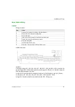
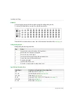
The input/output are wired to the connector (except the safeguarding inputs).
To connect the Base Station, respect the connector description:
If the ZARC03 external antenna is used, refer to the dedicated Instruction Sheet
.
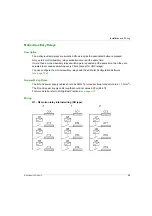
Safeguarding Inputs
Safeguarding inputs wiring procedure:
Input/Output Possible Uses
Step
Action
1
Unscrew the 4 screws at the bottom of the Base Station.
2
Remove the cover and insert a cable gland.
3
Remove the caps of cable gland.
4
Introduce the cable through the Base Station dedicated hole.
5
Connect the wires in the dedicated terminals.
6
Screw the cable gland.
7
Install the Base Station cover.
8
Screw the 4 screws to fasten the Base Station cover.
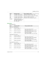
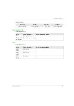
Input/Output
Possible uses (Depending of the configuration)
IN0
IN1…IN6
Detected Applicative Alarm
IN7…IN18
Safeguarding
S2_S3
Terminals for SIL2 / SIL3 E-STOP Configuration
Q0A, Q0B
Safety relay
Q1…Q9
Motion relays
Содержание eXLhoist
Страница 12: ...12 EIO0000001505 12 2014...
Страница 34: ...Wireless Remote Control System 34 EIO0000001505 12 2014...
Страница 52: ...52 EIO0000001505 12 2014...
Страница 146: ...Using The Wireless Remote Control System 146 EIO0000001505 12 2014...
Страница 151: ...Diagnostic EIO0000001505 12 2014 151 Procedure to Leave the Diagnostic Mode Step Action 1 Power OFF the Remote Device...
Страница 177: ...eXLhoist Configuration Software EIO0000001505 12 2014 177 The diagram illustrates the use cases...
Страница 200: ...eXLhoist Configuration Software 200 EIO0000001505 12 2014...
Страница 213: ...EIO0000001505 12 2014 213 Harmony eXLhoist EIO0000001505 04 2014 Appendices...
Страница 214: ...214 EIO0000001505 12 2014...


