Installation and Wiring
EIO0000001505 12/2014
111
Safety Relay
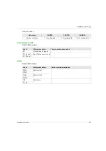
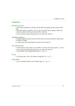
IN0 Safety Loop Input
The IN0 input is dedicated to check the correct actuator functionality with the auxiliary contact
state.
The E-STOP function can reach up to SIL 3 level only if all the relevant auxiliary contacts are
connected between the IN0 input and the S2_S3 port terminal.
The I/O and power supply cable lengths should not exceed 20 m (65.6 ft).
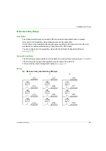
Q0A/Q0B Safety Relays
The safety relays are switched ON when ON/START/Horn button is activated and all the safety
conditions are fulfilled.
The safety relay output cable length should not exceed 20 m (65.6 ft).
General Wiring Rules
The I/O and power supply cables should be AWG 16 (cross-sectional conductor area = 1.3 mm
2
).
The I/O and power supply cable lengths should not exceed 20 m (65.6 ft).
For more details, refer to Wiring Best Practices
.
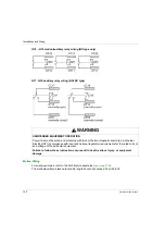
Wiring
For wiring examples, refer to the Architecture examples
Safety Details
For more details about safety, refer to Safety chapter
Содержание eXLhoist
Страница 12: ...12 EIO0000001505 12 2014...
Страница 34: ...Wireless Remote Control System 34 EIO0000001505 12 2014...
Страница 52: ...52 EIO0000001505 12 2014...
Страница 146: ...Using The Wireless Remote Control System 146 EIO0000001505 12 2014...
Страница 151: ...Diagnostic EIO0000001505 12 2014 151 Procedure to Leave the Diagnostic Mode Step Action 1 Power OFF the Remote Device...
Страница 177: ...eXLhoist Configuration Software EIO0000001505 12 2014 177 The diagram illustrates the use cases...
Страница 200: ...eXLhoist Configuration Software 200 EIO0000001505 12 2014...
Страница 213: ...EIO0000001505 12 2014 213 Harmony eXLhoist EIO0000001505 04 2014 Appendices...
Страница 214: ...214 EIO0000001505 12 2014...

