3
|
Components
Service manual
281
REYQ8~20+REMQ5U7Y1B
VRV IV+ Heat Recovery
ESIE18-15B – 2020.05
a
a
a
a
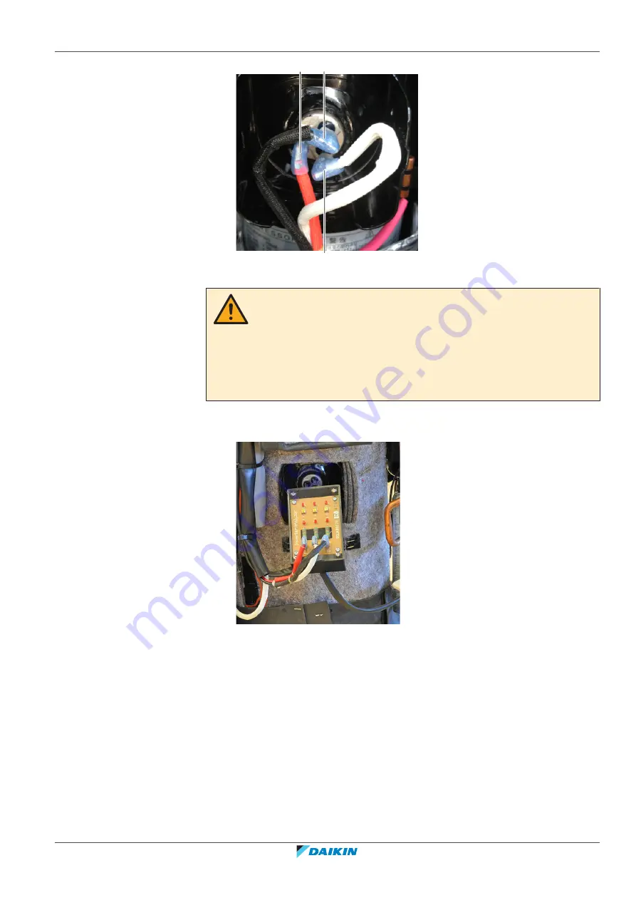
Faston connector
CAUTION
Power transistor check mode is activated ONLY on the main PCB of the main outdoor
unit. When there is more than 1 compressor in the unit or if the system is a
multi‑combination, all inverter PCB’s will perform a power transistor check. All
compressor wiring of all available compressors MUST be disconnected and safely
secured before power transistor check mode is activated. Do NOT touch the
compressor wiring and do NOT short‑circuit to ground through unit casing. Secure
the compressor wiring to avoid touching them accidentally.
4
Connect the Faston connectors to the Inverter Analyzer (SPP number
1368521).
a
Inverter checker
e
2 LEDs for phase U
b
Faston terminal U
f
2 LEDs for phase V
c
Faston terminal V
g
2 LEDs for phase W
d
Faston terminal W
5
Turn ON the power of the unit.
6
Activate power transistor check mode by applying field setting 2-28=1.
Result:
If all 6 LEDs on inverter checker module blink, then it means that the
transistors on the inverter PCB switch correctly.
7
To exit the power transistor check mode, set 2-28=0.
Result:
2 LEDs on inverter checker module for V phase will indicate the
discharge status of the DC voltage.
8
Wait until the LEDs are OFF before disconnecting U, V and W connections
from the inverter checker.
Содержание VRV IV+
Страница 473: ......
Страница 474: ......
Страница 475: ......
Страница 476: ...ESIE18 15B 2020 05 Copyright 2020 Daikin Verantwortung für Energie und Umwelt ...


