3
|
Components
Service manual
276
REYQ8~20+REMQ5U7Y1B
VRV IV+ Heat Recovery
ESIE18-15B – 2020.05
2
Check that all wires are properly connected and that all connectors are fully
plugged‑in.
3
Check that no connectors or wires are damaged.
4
Check that the wiring corresponds with the wiring diagram, see
385].
INFORMATION
Correct the wiring as needed.
Is the problem solved?
Action
Yes
No further actions required.
No
and continue with the next procedure.
To check the fuses of the inverter PCB
Prerequisite:
First perform all earlier checks of the inverter PCB, see
1
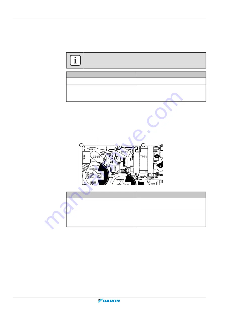
Measure the continuity of the fuse. If no continuity is measured, the fuse has
blown.
a
a
Fuse
Any blown fuses on the inverter PCB?
Action
Yes
Replace the inverter PCB, see
No
and continue with the next procedure.
To check the rectifier voltage of the inverter PCB
Prerequisite:
First perform all earlier checks of the inverter PCB, see
1
Turn ON the power of the unit.
For single fan units
2
Measure the voltage on the rectifier voltage check connector (a) X3A, located
above the power terminal assembly (b).
Result:
The measured voltage should be approximately 560 V DC.
Содержание VRV IV+
Страница 473: ......
Страница 474: ......
Страница 475: ......
Страница 476: ...ESIE18 15B 2020 05 Copyright 2020 Daikin Verantwortung für Energie und Umwelt ...


