Crestron
D3 Pro
™
Software
Step 5: Assign circuits to CLW wall-mounted dimmers/switches
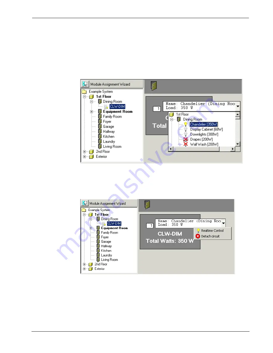
Select the CLW interface you want to connect. This will display a single output in the
program details area.
Click the arrow button next to the output and select the controlled circuit from the
drop-down list—if a circuit is not compatible it will be crossed out. As shown below,
this will turn the light bulb icon yellow, indicating that the circuit has been
successfully connected. This will also display the total wattage.
Use the same procedure to connect all the CLW interfaces in your project with the
desired circuits in your load schedule.
To disconnect a controlled circuit, right-click the output connection and select
Detach Circuit
from the submenu. The right-click submenu also provides a
Realtime Control
command. This allows you to adjust lighting levels in real time.
Step 6: Assign circuits to CLX modules
In the system directory, select the control module you want to connect. This will
display a list of outputs in the program detail area.
Reference Guide – DOC. 5998a
Crestron D3 Pro™
•
37


