Chapter 5: Installation
210
6
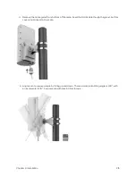
Continue with steps 9 and 10 above ensuring both cables
are secured to the center post with a tie wrap.
PMP 4 50 b High Gain – IP67
To convert an IP55 version of the PMP 450b High Gain to an IP67 version, kit N00000L135A is required.
This kit contains 4 off IP67 door/ glands. Follow the fitting instructions 1-5 in section PMP 450b High Gain –
IP55 Version above and then the steps below. Note that a permanent connection to the AUX port is not
available when using this kit.
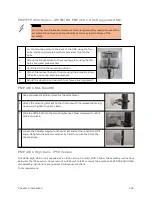
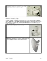
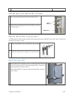
1
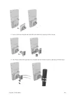
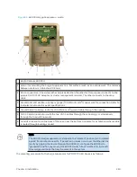
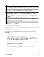
Locate an IP67 door/gland from kit N00000L135A.
2
Remove the cable gland from bottom cover. Feed the RJ45 cable
though the gland, bottom cover and connect to the radio.
Содержание PMP 450 Series
Страница 92: ...Chapter 2 System hardware 92 Figure 29 MicroPoP Omni antenna implementation pattern Vertical...
Страница 134: ...Chapter 3 System planning 134 Figure 51 Mast or tower installation...
Страница 135: ...Chapter 3 System planning 135 Figure 52 Wall installation...
Страница 136: ...Chapter 3 System planning 136 Figure 53 Roof installation...
Страница 137: ...Chapter 3 System planning 137 Figure 54 GPS receiver wall installation...
Страница 158: ...Chapter 3 System planning 158 Figure 61 cnMedusa Antenna...
Страница 258: ...Chapter 5 Installation 258 Figure 123 Yagi antenna alignment horizontally Figure 124 Yagi antenna alignment upward tilt...

