Chapter 5: Installation
205
PMP/ PTP 4 50 i Series – AP/ SM/ BH, PMP 4 50 3 GHz Ruggedized SM
Caution
Do not reverse the bracket clamp, as this arrangement may lead to failure of the
assembly. Do not over-tighten the bolts as this may lead to failure of the
assembly.
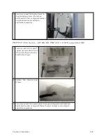
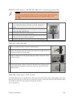
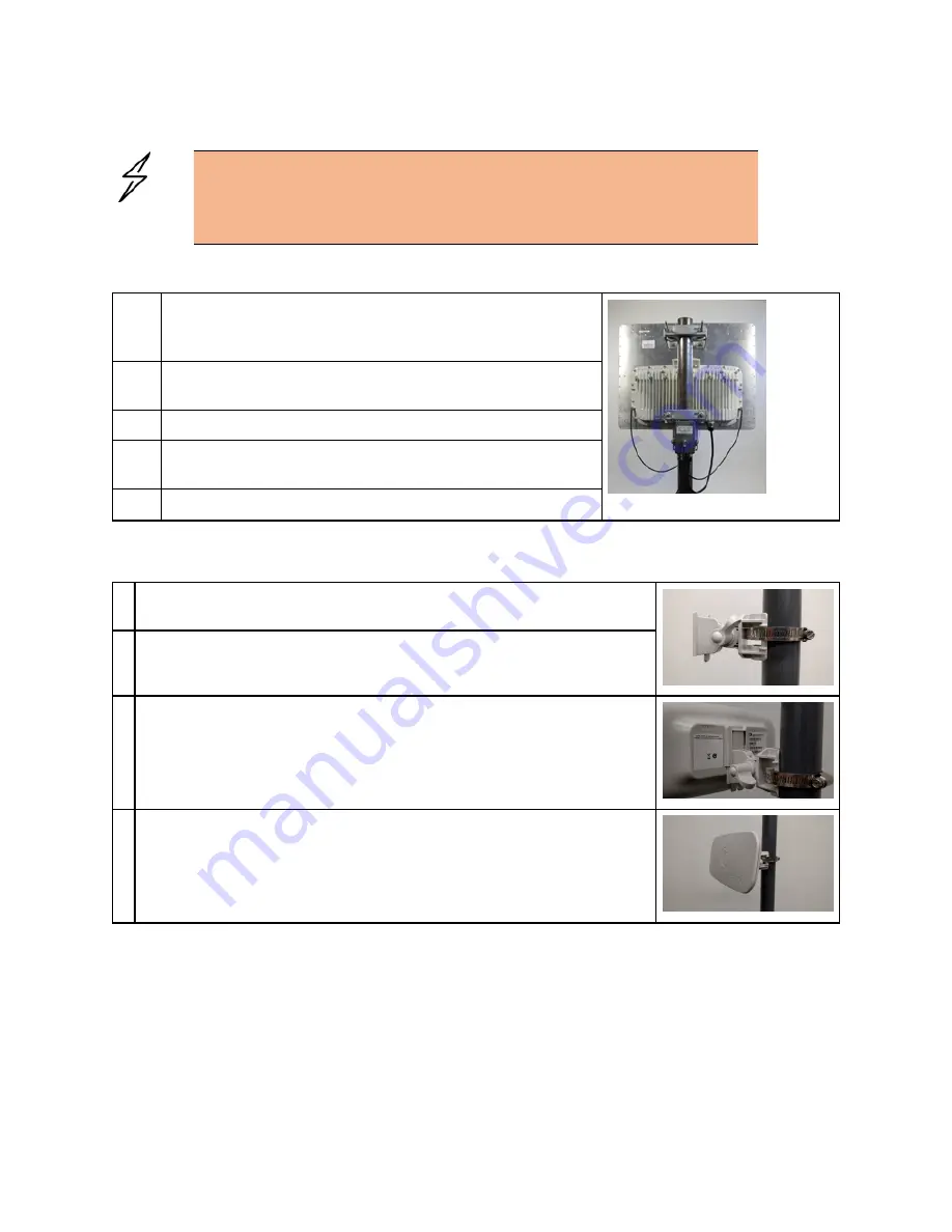
1
Fix the mounting plate to the back of the ODU using the four
bolts, and spring and plain washers provided. Tighten the
bolts.
2
Attach the bracket body to the mounting plate using the M8
bolt, spring and plain washers.
3
Hoist the ODU to the mounting position
4
Attach the bracket body to the pole using the bracket clamp,
M8 bolts, and spring and plain washers.
5
Adjust the elevation and azimuth to achieve visual alignment.
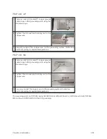
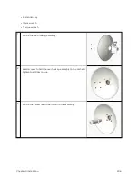
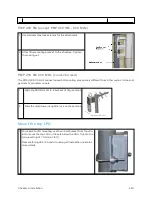
PMP 4 50 b Mid- Gain SM
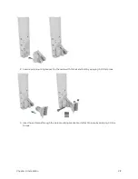
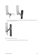
1
Use a stainless-steel hose clamp for the attachment.
2
Attach the mounting bracket to the structure with the release tab facing
downward. Tighten the hose clamp.
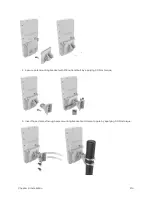
3
Slide the 450b SM onto the mounting bracket. Press downwards until it
clicks into place.
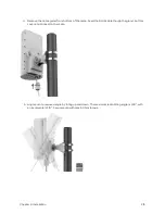
4
Loosen the adjuster wingnut on the bracket and set the required SM tilt
angle. Retighten the adjuster wingnut by hand to secure the SM at the
chosen angle.
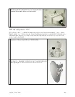
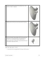
PMP 4 50 b High Gain – IP55 Version
The 450b High Gain unit is supplied as an IP55 version from Q4 2019. Follow the assembly instructions
below for the IP55 version. Conversion of an IP55 unit to IP67 requires the purchase of kit N000000L135A
and assembly instructions are covered in subsequent sections.
Tools required are:
Содержание PMP 450 Series
Страница 92: ...Chapter 2 System hardware 92 Figure 29 MicroPoP Omni antenna implementation pattern Vertical...
Страница 134: ...Chapter 3 System planning 134 Figure 51 Mast or tower installation...
Страница 135: ...Chapter 3 System planning 135 Figure 52 Wall installation...
Страница 136: ...Chapter 3 System planning 136 Figure 53 Roof installation...
Страница 137: ...Chapter 3 System planning 137 Figure 54 GPS receiver wall installation...
Страница 158: ...Chapter 3 System planning 158 Figure 61 cnMedusa Antenna...
Страница 258: ...Chapter 5 Installation 258 Figure 123 Yagi antenna alignment horizontally Figure 124 Yagi antenna alignment upward tilt...

