Chapter 2: System hardware
116
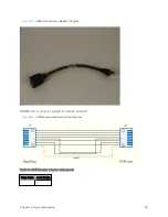
Plug J1 pin
Jack J2 pin
2
2
3
3
4
4
5
7
6
6
7
5
8
8
Screen
Screen
Note
Pins 5 and 7 are wired in a cross-over configuration.
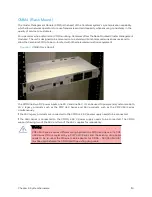
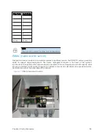
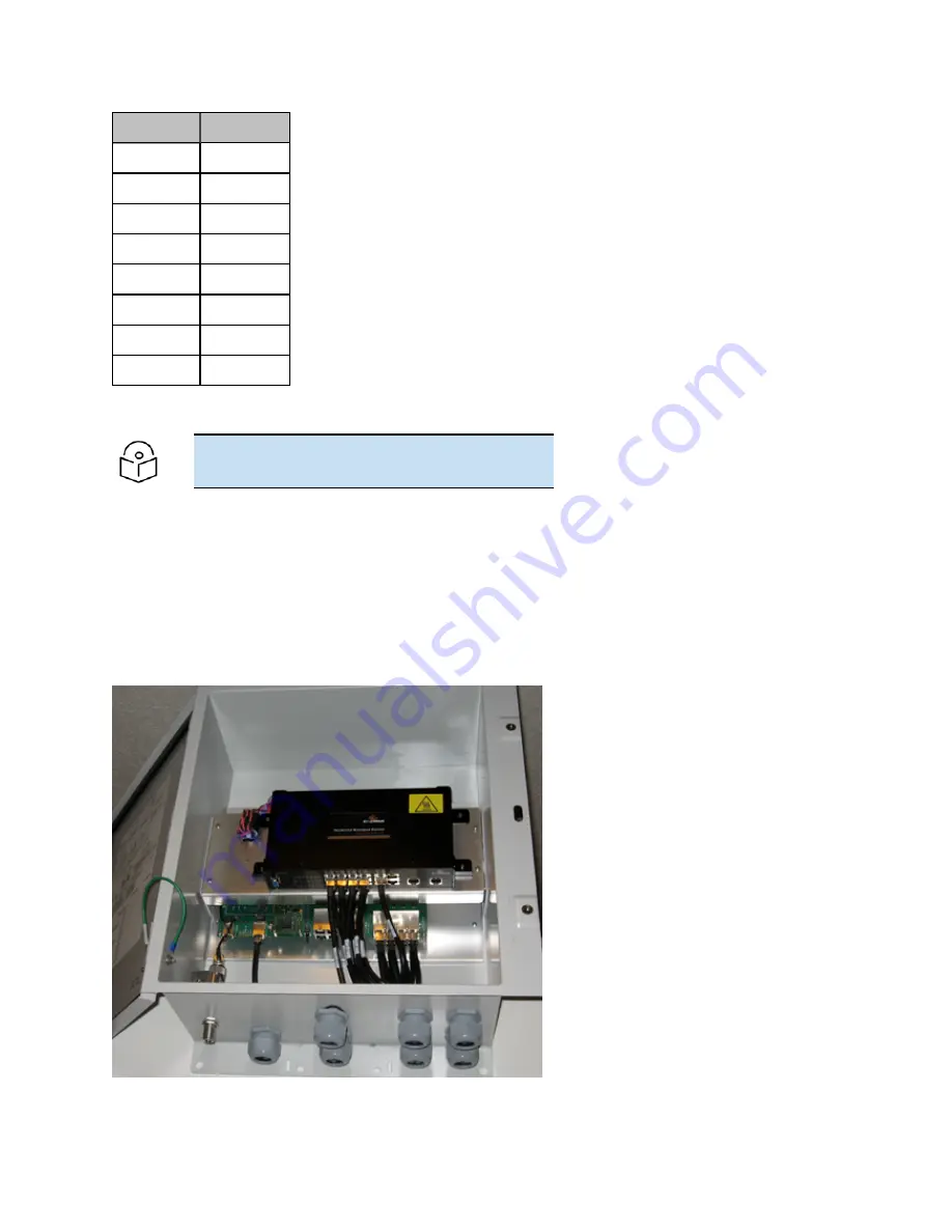
CMM4 ( Cab inet w it h sw it ch)
Designed to deliver consistent and reliable wireless broadband service, the PMP/PTP system gracefully
scales to support large deployments. The cluster management module is the heart of the system’s
synchronization capability which allows network operators to re-use frequencies and add capacity while
ensuring consistency in the quality of service to customers. As a result, subscribers can experience carrier-
grade service even at the outer edge of the network.
Figure 47 :
CMM4 (Cabinet with switch)
Содержание PMP 450 Series
Страница 92: ...Chapter 2 System hardware 92 Figure 29 MicroPoP Omni antenna implementation pattern Vertical...
Страница 134: ...Chapter 3 System planning 134 Figure 51 Mast or tower installation...
Страница 135: ...Chapter 3 System planning 135 Figure 52 Wall installation...
Страница 136: ...Chapter 3 System planning 136 Figure 53 Roof installation...
Страница 137: ...Chapter 3 System planning 137 Figure 54 GPS receiver wall installation...
Страница 158: ...Chapter 3 System planning 158 Figure 61 cnMedusa Antenna...
Страница 258: ...Chapter 5 Installation 258 Figure 123 Yagi antenna alignment horizontally Figure 124 Yagi antenna alignment upward tilt...

