Chapter 2: System hardware
129
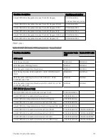
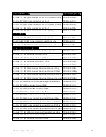
Cambium description
Cambium part number
PTP 450 900 MHz END – Connectorized
C009045B001A
PTP 450 3.5 GHz END – Integrated
C035045B001A
PTP 450 3.5 GHz END – Connectorized
C035045B002A
PTP 450 3.5 GHz END – Integrated – DES Only
C035045B003A
PTP 450 3.5 GHz END – Connectorized – DES Only
C035045B004A
PTP 450 3.65 GHz END – Integrated
C036045B001A
PTP 450 3.65 GHz END – Connectorized
C036045B002A
PTP 450 3.65 GHz END – Integrated – DES Only
C036045B003A
PTP 450 3.65 GHz END – Connectorized – DES Only
C036045B004A
PTP 450 5 GHz END – Integrated (ROW)
C054045B001A
PTP 450 5 GHz END – Connectorized (ROW)
C054045B002A
PTP 450 5 GHz END – Integrated (ROW) – DES Only
C054045B003A
PTP 450 5 GHz END – Connectorized (ROW) – DES Only
C054045B004A
PTP 450 5 GHz END – Integrated (FCC)
C054045B005A
PTP 450 5 GHz END – Connectorized (FCC)
C054045B006A
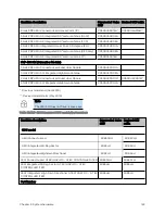
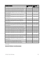
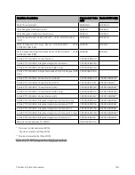
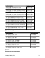
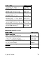
PMP/ PTP 4 50 / 4 50 i Series Accessories
Table 97 :PMP/PTP 450/450i Series Accessories
Cambium description
Cambium part number
PMP 450 AP Antenna Options
900 MHz 65 degree Sector Antenna (Dual Slant)
N009045D001A
900 MHz 12 dBi gain directional antenna (Dual Slant)
N009045D003A
2.4 GHz Dual Slant Antenna for 60 Degree Sector
C024045D601A
3.5 GHz and 3.6 GHz Dual Slant Antenna for 90 Degree Sector
C030045D901A
5 GHz Antenna for 60 Degree Sector
85009325001
5 GHz Antenna for 90 Degree Sector
85009324001
N-type to N-type cable (16-inch length)
30009406002
Power supplies
Power supply, 60 W, 56 V with Gbps support
N000065L001B
AC+DC Enhanced Power Injector
C000065L002C
Содержание PMP 450 Series
Страница 92: ...Chapter 2 System hardware 92 Figure 29 MicroPoP Omni antenna implementation pattern Vertical...
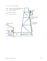
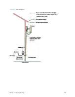
Страница 134: ...Chapter 3 System planning 134 Figure 51 Mast or tower installation...
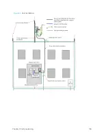
Страница 135: ...Chapter 3 System planning 135 Figure 52 Wall installation...
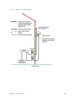
Страница 136: ...Chapter 3 System planning 136 Figure 53 Roof installation...
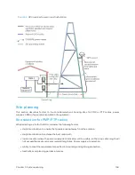
Страница 137: ...Chapter 3 System planning 137 Figure 54 GPS receiver wall installation...
Страница 158: ...Chapter 3 System planning 158 Figure 61 cnMedusa Antenna...
Страница 258: ...Chapter 5 Installation 258 Figure 123 Yagi antenna alignment horizontally Figure 124 Yagi antenna alignment upward tilt...

