Chapter 5: Installation
233
1
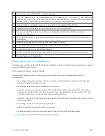
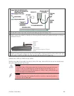
Cut the drop cable to the length required from bottom LPU to PSU.
2
At the LPU end only:
l
Fit one cable gland and one RJ45 connector by following the procedure Terminate with RJ45
connectors.
l
Connect this cable and gland to the bottom LPU.
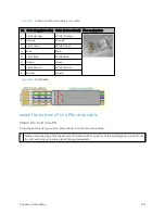
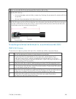
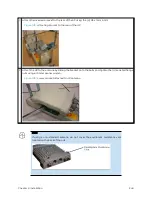
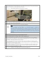
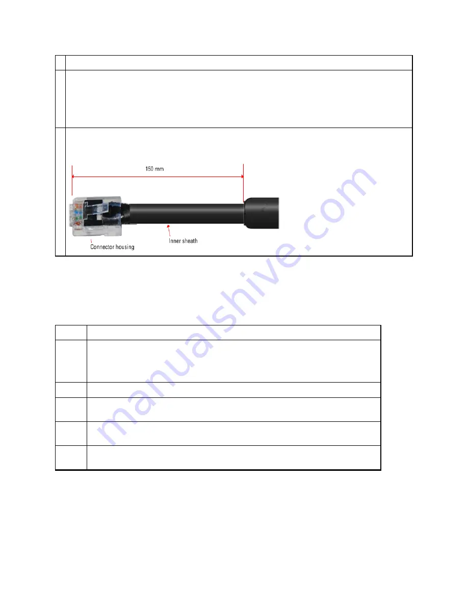
3 At the PSU end only: Do not fit a cable gland. Strip the cable outer sheath and fit the RJ45 connector
load bar. Fit the RJ45 connector housing. To ensure there is effective strain relief, locate the cable
inner sheath under the connector housing tang:
Inst alling ext ernal ant ennas t o a co nnect o rized ODU
PMP 4 50 i Ser ies
To mount and connect an external antenna to the connectorized ODU, proceed as follows:
1
Mount the antenna(s) according to manufacturer’s instructions.
2
Connect the ODU A and B interfaces to the antenna(s) with RF cable of type
LMR-400 (Cambium part numbers 30010194001 and 30010195001) and N type
connectors (Cambium part number 09010091001). Tighten the N type connectors to
a torque setting of 1.7 Nm (1.3 lb ft).
3
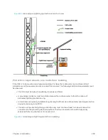
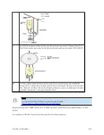
If the ODU is mounted indoors, install lightning arrestors at the building entry point:
4
Form drip loops near the lower ends of the antenna cables. These ensure that water is
not channeled towards the connectors.
5
If the ODU is mounted outdoors, weatherproof the N type connectors (when antenna
alignment is complete) using PVC tape and self-amalgamating rubber tape.
6
Weatherproof the antenna connectors in the same way (unless the antenna
manufacturer specifies a different method).
Содержание PMP 450 Series
Страница 92: ...Chapter 2 System hardware 92 Figure 29 MicroPoP Omni antenna implementation pattern Vertical...
Страница 134: ...Chapter 3 System planning 134 Figure 51 Mast or tower installation...
Страница 135: ...Chapter 3 System planning 135 Figure 52 Wall installation...
Страница 136: ...Chapter 3 System planning 136 Figure 53 Roof installation...
Страница 137: ...Chapter 3 System planning 137 Figure 54 GPS receiver wall installation...
Страница 158: ...Chapter 3 System planning 158 Figure 61 cnMedusa Antenna...
Страница 258: ...Chapter 5 Installation 258 Figure 123 Yagi antenna alignment horizontally Figure 124 Yagi antenna alignment upward tilt...

