Chapter 1: Product description
36
l
All power injectors / power supplies in the Cambium Networks range are designed for an
indoor environment.
l
Different ODUs require different power requirements, so be sure to select the correct power
supply.
l
Surge protection units: A range of surge protectors is available to suit different ODUs
l
The Gigabit Surge Suppressor provides a path to ground (Protective Earth) that protects
connected radio equipment from near-miss lightning strikes.
l
Lightning protection unit (LPU): LPUs are installed in the ports copper drop cables to
provide transient voltage surge suppression.
l
A DC lightning protection unit (LPU) provides transient voltage surge suppression for 3 GHz
PMP 450.
l
Cabling:
l
AC line cords: AC line cords are supplied separately from the power supply. Regional
variants are available.
l
Antennas and antenna cabling: Connectorized ODUs require RF cables to connect to
external antennas.
l
Ethernet cabling: All configurations require a copper Ethernet Cat5e connection from the
ODU (Ethernet port) to the PoE.
l
Ground cables: ODU, LPUs and outdoor copper Ethernet cables are bonded to the site
grounding system using ground cables.
For more information about these components, including interfaces, specifications and Cambium part
numbers, refer to Chapter 2: System hardware.
W ireless o p erat io n
This section describes how the 450 Platform Family wireless link is operated, including modulation modes,
power control and security.
Tim e d ivision d up lexing
The system uses Time Division Duplexing (TDD) – one channel alternately transmits and receives rather
than using one channel for transmitting and a second channel for receiving. The radio link operates on a
single frequency channel in each direction using TDD. The AP operates in TDMA mode to service multiple
SMs. To accomplish TDD, the AP/BHM must provide sync to its SM/BHS. Furthermore, collocated
APs/BHMs must be synced together – an unsynchronized AP/BHM that transmits during the receive cycle
of a collocated AP/BHM can prevent a second AP/BHM from being able to decode the signals from its
APs/BHSs. In addition, across a geographical area, APs/BHMs that can “hear” each other benefit from
using a common sync to further reduce self-interference within the network.
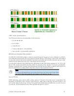
Modules use TDD on a common frequency to divide frames for uplink (orange) and downlink (green)
usage, as shown in the figure below.
For more information on synchronization configuration options, see GPS synchronization on page 1.
Figure 2 :
TDD frame division
Содержание PMP 450 Series
Страница 92: ...Chapter 2 System hardware 92 Figure 29 MicroPoP Omni antenna implementation pattern Vertical...
Страница 134: ...Chapter 3 System planning 134 Figure 51 Mast or tower installation...
Страница 135: ...Chapter 3 System planning 135 Figure 52 Wall installation...
Страница 136: ...Chapter 3 System planning 136 Figure 53 Roof installation...
Страница 137: ...Chapter 3 System planning 137 Figure 54 GPS receiver wall installation...
Страница 158: ...Chapter 3 System planning 158 Figure 61 cnMedusa Antenna...
Страница 258: ...Chapter 5 Installation 258 Figure 123 Yagi antenna alignment horizontally Figure 124 Yagi antenna alignment upward tilt...

