Chapter 3: System planning
161
The 450 Platform Family is designed to operate in Non- Line- of- Sight (NLoS) and Line- of- Sight (LoS)
environments. An NLOS environment is one in which there is no optical line-of-sight, that is, there are
obstructions between the antennas.
OFDM technology can often use multi-pathing to an advantage to overcome nLOS, especially in cases
where the Fresnel zone is only partially blocked by buildings, “urban canyons”, or foliage. OFDM tends to
help especially when obstacles are near the middle of the link, and less so when the obstacles are very near
the ODU.
However, attenuation through walls and trees is substantial for any use of the 5.4 GHz and 5.8 GHz
frequency bands. The lower frequency radio waves of 900 MHz radios provide greater penetration
through walls, trees and other obstacles, making it optimal for most non-line-of-sight applications. Even
with OFDM, these products are not expected to penetrate walls or extensive trees and foliage.
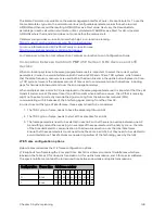
Pat h loss
Path loss is the amount of attenuation the radio signal undergoes between the two ends of the link. The
path loss is the sum of the attenuation of the path if there were no obstacles in the way (Free Space Path
Loss), the attenuation caused by obstacles (Excess Path Loss) and a margin to allow for possible fading of
the radio signal (Fade Margin). The following calculation needs to be performed to judge whether a link
can be installed:
Where:
Is:
Free Space Path Loss (dB)
Excess Path Loss (dB)
Fade Margin Required (dB)
Seasonal Fading (dB)
Equipment Capability (dB)
Calculat ing Link Loss
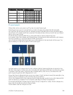
The link loss is the total attenuation of the wireless signal between two point-to-multipoint units. The link
loss calculation is presented below:
Link Loss (dB) = Transmit power of the remote wireless unit (dBm)
−
Tx Cable loss (dB)
−
Received
power at the local unit (dBm) – Rx cable loss (dB) + Antenna gain at the remote unit (dBi) + Antenna gain
at the local unit (dBi)
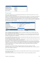
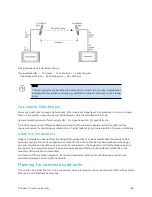
Calculat ing Rx Sig nal Level
The determinants in Rx signal level are illustrated in System planning. Below figure determinants in Rx
signal level
Содержание PMP 450 Series
Страница 92: ...Chapter 2 System hardware 92 Figure 29 MicroPoP Omni antenna implementation pattern Vertical...
Страница 134: ...Chapter 3 System planning 134 Figure 51 Mast or tower installation...
Страница 135: ...Chapter 3 System planning 135 Figure 52 Wall installation...
Страница 136: ...Chapter 3 System planning 136 Figure 53 Roof installation...
Страница 137: ...Chapter 3 System planning 137 Figure 54 GPS receiver wall installation...
Страница 158: ...Chapter 3 System planning 158 Figure 61 cnMedusa Antenna...
Страница 258: ...Chapter 5 Installation 258 Figure 123 Yagi antenna alignment horizontally Figure 124 Yagi antenna alignment upward tilt...

