Chapter 5: Installation
231
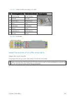
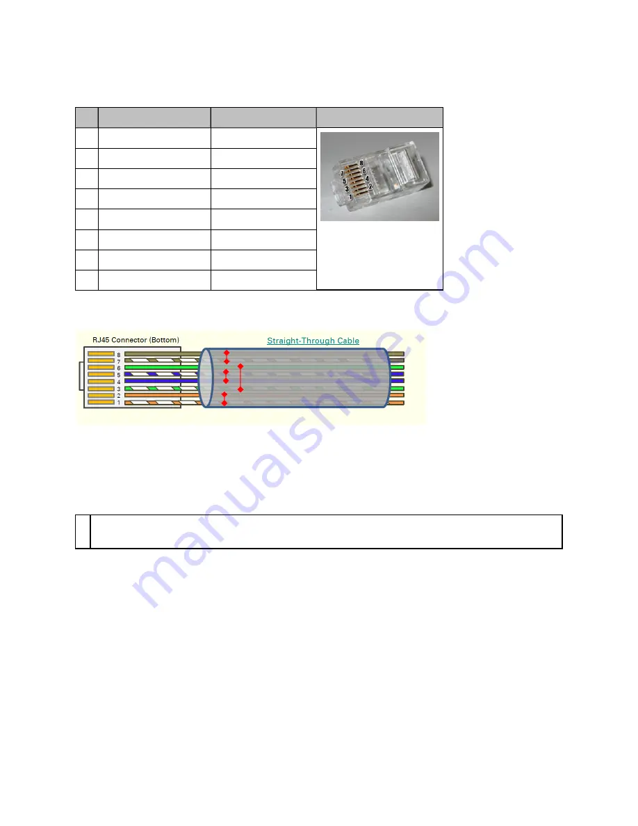
Figure 87 :
RJ45 connector and cable color code
Pin Color (Supplied cable)
Color (Conventional)
Pins on plug face
1
Light Orange
White/Orange
2
Orange
Orange
3
Light Green
White/Green
4
Blue
Blue
5
Light Blue
White/Blue
6
Green
Green
7
Light Brown
White/Brown
8
Brown
Brown
Figure 88 :
RJ45 cable
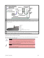
Inst all t he b ot t om LPU t o PSU d r op cab le
Inst all t he bot t om LPU
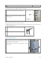
Install the bottom LPU, ground it, and connect it to the main drop cable.
1
Select a mounting point for the bottom LPU within 600 mm (24 in) of the building entry point. Mount
the LPU vertically with cable glands facing downwards.
Содержание PMP 450 Series
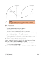
Страница 92: ...Chapter 2 System hardware 92 Figure 29 MicroPoP Omni antenna implementation pattern Vertical...
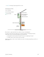
Страница 134: ...Chapter 3 System planning 134 Figure 51 Mast or tower installation...
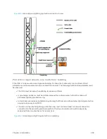
Страница 135: ...Chapter 3 System planning 135 Figure 52 Wall installation...
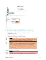
Страница 136: ...Chapter 3 System planning 136 Figure 53 Roof installation...
Страница 137: ...Chapter 3 System planning 137 Figure 54 GPS receiver wall installation...
Страница 158: ...Chapter 3 System planning 158 Figure 61 cnMedusa Antenna...
Страница 258: ...Chapter 5 Installation 258 Figure 123 Yagi antenna alignment horizontally Figure 124 Yagi antenna alignment upward tilt...

