Chapter 4: Preparing for installation
197
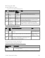
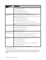
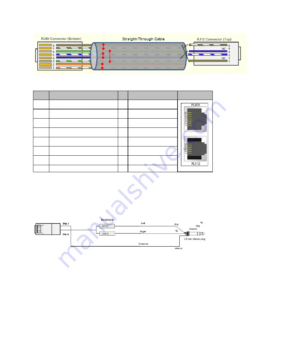
Table 122 :AP/BHM to UGPS cable pinout
Pin
450i Series AP RJ 45 Connector
Pin UGPS RJ 12 Connector
Connector
1
NC
1
8 on RJ 45
2
NC
2
NC
3
NC
3
5 on RJ 45
4
4 on RJ 12
4
4 on RJ 45
5
3 on RJ 12
5
NC
6
NC
6
7 on RJ 45
7
6 on RJ 12
8
1 on RJ 12
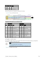
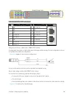
Alignment t one cable ( for PMP/ PTP 4 50 i)
The alignment tone cable is constructed using RJ45 plug and Stereo plug. The pin configuration is shown
in Alignment tone cable pin configuration
Figure 78 :
Alignment tone cable pin configuration
For more information, refer Aux port to alignment tone headset wiring.
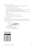
O verride plug cable ( for PMP 4 50 only)
To construct an override plug, perform the following steps:
l
Crimp an RJ-12 6 pins connector onto a 6-inch length of CAT 5 cable
l
Pin out all 6 pins
l
Short (solder together) pins 4 and 6 on the other end. Do not connect any other wires to anything.
Figure 79 :
RJ-12 pinout for the default plug
Содержание PMP 450 Series
Страница 92: ...Chapter 2 System hardware 92 Figure 29 MicroPoP Omni antenna implementation pattern Vertical...
Страница 134: ...Chapter 3 System planning 134 Figure 51 Mast or tower installation...
Страница 135: ...Chapter 3 System planning 135 Figure 52 Wall installation...
Страница 136: ...Chapter 3 System planning 136 Figure 53 Roof installation...
Страница 137: ...Chapter 3 System planning 137 Figure 54 GPS receiver wall installation...
Страница 158: ...Chapter 3 System planning 158 Figure 61 cnMedusa Antenna...
Страница 258: ...Chapter 5 Installation 258 Figure 123 Yagi antenna alignment horizontally Figure 124 Yagi antenna alignment upward tilt...

