Chapter 3: System planning
140
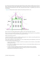
over the structure. Where the sphere rests against the ground and a strike termination device (such as a
finial or ground bar), all the space under the sphere is considered to be in the zone of protection (Zone B).
Similarly, where the sphere rests on two finials, the space under the sphere is considered to be in the zone
of protection.
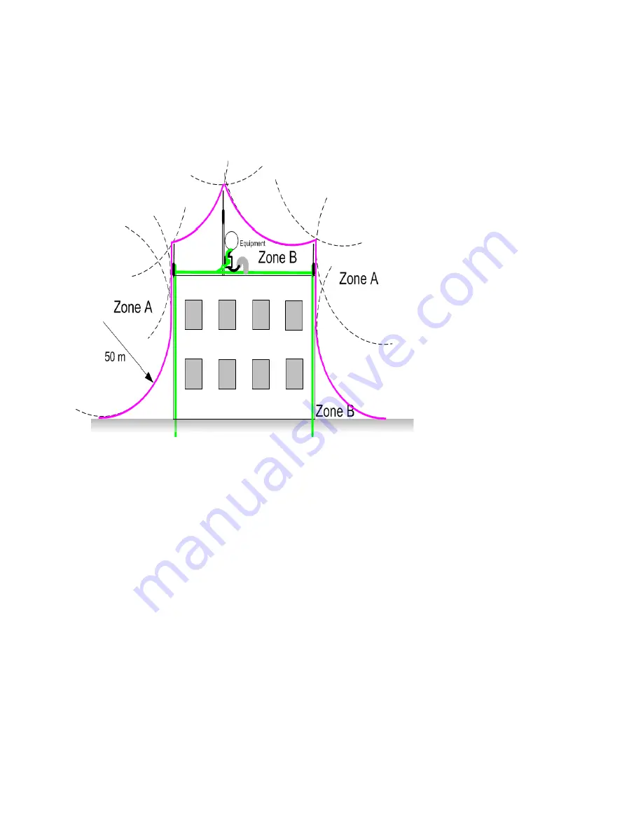
Figure 56 :
Rolling sphere method to determine the lightning protection zones
Zone A: In this zone a direct lightning strike is possible. Do not mount equipment in this zone.
Zone B: In this zone, direct EMD (lightning) effects are still possible, but mounting in this zone significantly
reduces the possibility of a direct strike. Mount equipment in this zone.
Sit e grounding syst em
Confirm that the site has a correctly installed grounding system on a common ground ring with access
points for grounding the 450 Platform Family ODU.
If the outdoor equipment is to be installed on the roof of a high building (Roof installation), confirm that
the following additional requirements are met:
l
A grounding conductor is installed around the roof perimeter to form the main roof perimeter
lightning protection ring.
l
Air terminals are installed along the length of the main roof perimeter lightning protection ring,
typically every 6.1m (20ft).
l
The main roof perimeter lightning protection ring contains at least two down conductors
connected to the grounding electrode system. The down conductors should be physically
separated from one another, as far as practical.
Содержание PMP 450 Series
Страница 92: ...Chapter 2 System hardware 92 Figure 29 MicroPoP Omni antenna implementation pattern Vertical...
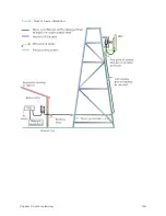
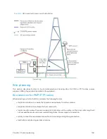
Страница 134: ...Chapter 3 System planning 134 Figure 51 Mast or tower installation...
Страница 135: ...Chapter 3 System planning 135 Figure 52 Wall installation...
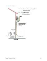
Страница 136: ...Chapter 3 System planning 136 Figure 53 Roof installation...
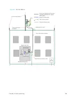
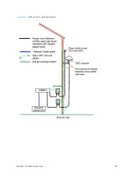
Страница 137: ...Chapter 3 System planning 137 Figure 54 GPS receiver wall installation...
Страница 158: ...Chapter 3 System planning 158 Figure 61 cnMedusa Antenna...
Страница 258: ...Chapter 5 Installation 258 Figure 123 Yagi antenna alignment horizontally Figure 124 Yagi antenna alignment upward tilt...

