Chapter 2: System hardware
117
CMM4 ( Cab inet w it hout sw it ch)
This CMM includes all the functionality listed above but there is no switch. This provides the network
operator the flexibility to use the switch of their choice with the power and synchronization capabilities of
the CMM4.
CMM3/ CMMm icr o
The CMM3 or CMMmicro (Cluster Management Module micro) provides power, GPS timing, and
networking connections for an AP cluster. The CMM3 is configurable through a web interface.
The CMM3 contains an 8-port managed switch that supports Power over Ethernet (PoE – this is Cambium
PoE, not the standard PoE) on each port and connects any combination of APs, BHMs, BHSs, or Ethernet
feed. The Cambium fixed wireless broadband IP networks PoE differs from IEEE Standard 803.3af PoE,
and the two should not be intermixed. The CMM3 can auto-negotiate speed to match inputs that are either
100BASE-TX or 10BASE-T, and either full duplex or half duplex, where the connected device is set to auto-
negotiate. Alternatively, these parameters are settable.
A CMM3 requires only one cable, terminating in an RJ45 connector, for each connected module to
distribute
l
Ethernet signaling.
l
power to as many as 8 co-located modules—APs, BHMs, or BHSs. Through a browser interface to
the managed switch, ports can be powered or not.
l
sync to APs and BHMs. The CMM3 receives 1-pulse per second timing information from Global
Positioning System (GPS) satellites through an antenna (included) and passes the timing pulse
embedded in the 24 V power to the connected modules.
GPS status information is available at the CMM3, however
l
CMM3 provides time and date information to BHMs and APs if both the CMMmicro is operating on
CMMmicro Release 2.1 or later and the AP/BHM is operating on System Release 4.2 or later. See
Configuring Time Settings in Configuration Guide for more details.
l
CMM3 does not provide time and date information to BHMs and APs if either the CMM3 is operating
on a release earlier than CMMmicro Release 2.1 or the AP/BHM is operating on a release earlier than
System Release 4.2.
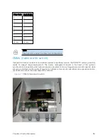
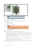
A CMM3/CMMicro is shown in CMM3 and Pole mounted CMM3.
Figure 48 :
CMM3
Figure 49 :
Pole mounted CMM3
Содержание PMP 450 Series
Страница 92: ...Chapter 2 System hardware 92 Figure 29 MicroPoP Omni antenna implementation pattern Vertical...
Страница 134: ...Chapter 3 System planning 134 Figure 51 Mast or tower installation...
Страница 135: ...Chapter 3 System planning 135 Figure 52 Wall installation...
Страница 136: ...Chapter 3 System planning 136 Figure 53 Roof installation...
Страница 137: ...Chapter 3 System planning 137 Figure 54 GPS receiver wall installation...
Страница 158: ...Chapter 3 System planning 158 Figure 61 cnMedusa Antenna...
Страница 258: ...Chapter 5 Installation 258 Figure 123 Yagi antenna alignment horizontally Figure 124 Yagi antenna alignment upward tilt...

