Chapter 2: System hardware
95
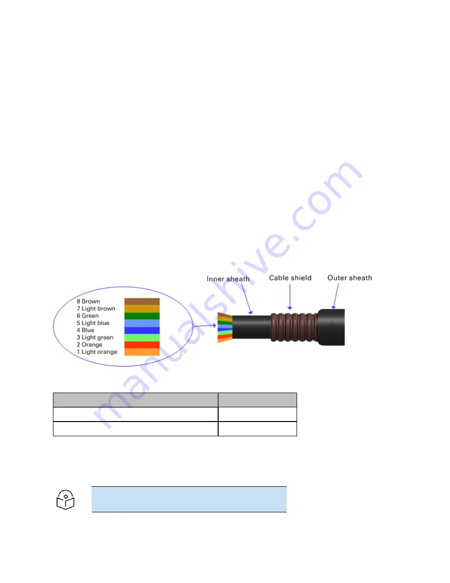
Out d oor cop p er Cat 5e Et her net cab le
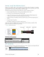
Outdoor Cat 5e cable is used for all connections that terminate outside the building. For example,
connections between the ODU, surge suppressors (if installed), UGPS receivers (if installed) and the power
supply injector. This is known as a “drop cable” (Outdoor drop cable).
The following practices are essential to the reliability and longevity of cabled connections:
l
Use only shielded cables and connectors to resist interference and corrosion.
l
For vertical runs, provide cable support and strain relief.
l
Include a 2 ft (0.6 m) service loop on each end of the cable to allow for thermal expansion and
contraction and to facilitate terminating the cable again when needed.
l
Include a drip loop to shed water so that most of the water does not reach the connector at the
device.
l
Properly crimp all connectors.
l
Use dielectric grease on all connectors to resist corrosion.
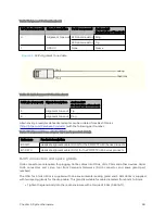
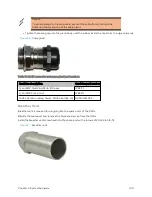
Order Superior Essex type BBDGe cable from Cambium Networks (Drop cable part numbers). Other
lengths of this cable are available from Superior Essex.
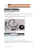
Figure 31 :
Outdoor drop cable
Table 65 :Drop cable part numbers
Cambium description
Cambium part number
1000 ft Reel Outdoor Copper Clad CAT5E
WB3175
328 ft (100 m) Reel Outdoor Copper Clad CAT5E
WB3176
SFP m od ule kit s
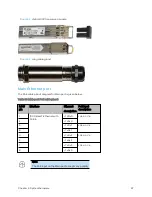
SFP module kits allow connection of a PMP 450 Series ODU to a network over an Optical Gigabit Ethernet
interface (1000BASE-LX or 1000BASE-SX) full-duplex mode.
Note
PMP 450m supports Fiber SFPs from system release 15.0.3.
Содержание PMP 450 Series
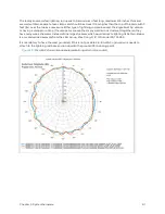
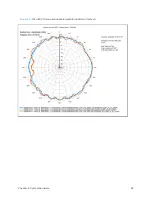
Страница 92: ...Chapter 2 System hardware 92 Figure 29 MicroPoP Omni antenna implementation pattern Vertical...
Страница 134: ...Chapter 3 System planning 134 Figure 51 Mast or tower installation...
Страница 135: ...Chapter 3 System planning 135 Figure 52 Wall installation...
Страница 136: ...Chapter 3 System planning 136 Figure 53 Roof installation...
Страница 137: ...Chapter 3 System planning 137 Figure 54 GPS receiver wall installation...
Страница 158: ...Chapter 3 System planning 158 Figure 61 cnMedusa Antenna...
Страница 258: ...Chapter 5 Installation 258 Figure 123 Yagi antenna alignment horizontally Figure 124 Yagi antenna alignment upward tilt...

