Chapter 3: System planning
149
The Frame Calculator is available on the web management interface Tools > Frame Calculator. To use the
Frame Calculator, type into the calculator various configurable parameter values for each proximal
AP/BHM and then record the resulting AP/BHM Receive Start value. Next vary the Downlink Data
percentage in each calculation and iterate until a calculated AP/BHM Receive Start for all co-located
AP/BHMs where the transmit end does not come before the receive start.
Cambium also provides co-location tool which helps in co-location planning:
https://support.cambiumnetworks.com/files/colocationtool
For more information on 450 Platform Family co-location, see
http://www.cambiumnetworks.com/solution-papers
For Cambium co-location tool refer section Cambium co-location tool in Configuration Guide.
Co- locat ion bet w een Cambium PMP 4 50 Series 3 GHz devices and LTE
devices
When co-locating systems in the same geographical area it is important to select the correct system
parameters in order to avoid interference. Both Cambium PMP and LTE are TDD systems, which means
that the same frequency resources are used both in the downlink and in the uplink but multiplexed in time.
A TDD cycle or frame, is the minimum amount of time used to communicate in both directions, including
gaps for hardware turnaround and over the air propagation delays.
When multiple access points (APs) are deployed in the same geographical area, it is important that they all
transmit and receive at the same time. If one AP transmits when another receives, the AP that is receiving
might not be able to correctly decode the signal coming from the subscriber modules (SMs)
communicating with it, because of the interfering signal coming from the other AP.
In order to avoid this type of interference, three aspects need to be considered:
1. The TDD cycle, or frame, needs to have the same length for all APs
2. The TDD cycle, or frame, needs to start at the same time for all APs
3. The frame parameters need to be selected in each AP so that there is no overlap between one AP
transmitting and another receiving. An example of these parameters is the duty cycle, i.e. the ratio
of the time dedicated to communication in the downlink direction over the total time frame.
Ensure that these parameters do not need to be the same in all APs, but they need to be selected to
avoid interference. These features are needed regardless of the technology used by the APs.
LTE frame configuration options
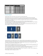
Below table summarizes the LTE frame configuration options.
LTE supports two frame lengths, 5 ms and 10 ms. Each 10 ms interval contains 10 subframes, which are
labeled in the Table as D for downlink transmission, U for uplink transmission, and S for special subframe.
The special subframe contains the turnaround time between downlink and uplink transmissions.
Configuration Frame time
Subframe number
0
1
2
3
4
5
6
7
8
9
0
5 ms
D S
U
U
U
D S
U
U
U
1
5 ms
D S
U
U
D D S
U
U
D
Содержание PMP 450 Series
Страница 92: ...Chapter 2 System hardware 92 Figure 29 MicroPoP Omni antenna implementation pattern Vertical...
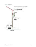
Страница 134: ...Chapter 3 System planning 134 Figure 51 Mast or tower installation...
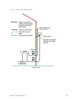
Страница 135: ...Chapter 3 System planning 135 Figure 52 Wall installation...
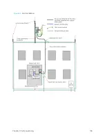
Страница 136: ...Chapter 3 System planning 136 Figure 53 Roof installation...
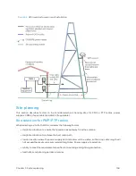
Страница 137: ...Chapter 3 System planning 137 Figure 54 GPS receiver wall installation...
Страница 158: ...Chapter 3 System planning 158 Figure 61 cnMedusa Antenna...
Страница 258: ...Chapter 5 Installation 258 Figure 123 Yagi antenna alignment horizontally Figure 124 Yagi antenna alignment upward tilt...

