Chapter 3: System planning
172
l
Managing module access by passwords
l
Filtering protocols and ports
l
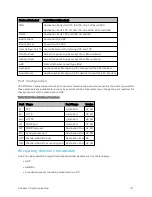
Port Configuration
Isolat ing A P/ BHM f r om t he Int er net
Ensure that the IP addresses of the AP/BHM in the network:
l
are not routable over the Internet.
l
do not share the subnet of the IP address of your user.
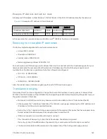
RFC 1918, Address Allocation for Private Subnets, reserves for private IP networks three blocks of IP
addresses that are not routable over the Internet:
l
/8 subnets have one reserved network, 10.0.0.0 to 10.255.255.255.
l
/16 subnets have 16 reserved networks, 172.16.0.0 to 172.31.255.255.
l
/24 subnets have 256 reserved networks, 192.168.0.0 to 192.168.255.255.
Encr yp t ing r ad io t r ansm issions
Cambium fixed wireless broadband IP systems employ the following form of encryption for security of the
wireless link:
AES (Advanced Encryption Standard): An over-the-air link encryption option that uses the Rijndael
algorithm and 128-bit keys to establish a higher level of security than DES. AES products are certified as
compliant with the Federal Information Processing Standards (FIPS 197) in the U.S.A.
The default encryption setting for 450 Platform Family ODU is "None".
Planning f or HTTPS op er at ion
Before starting to configure HTTPS operation, ensure that the cryptographic material listed in HTTPS
security material is available.
Table 113 : HTTPS security material
Item
Description
Quantity required
User Defined
Security Banner
The banner provides warnings and notices to be read by the
user before logging in to the ODU. Use text that is
appropriate to the network security policy.
Normally one per link.
This depends upon
network policy.
Port numbers
for HTTP,
HTTPS and
Telnet
Port numbers allocated by the network.
As allocated by
network.
Planning f or SNMPv3 op er at ion
SNMP securit y mode
Decide how SNMPv3 security will be configured.
Содержание PMP 450 Series
Страница 92: ...Chapter 2 System hardware 92 Figure 29 MicroPoP Omni antenna implementation pattern Vertical...
Страница 134: ...Chapter 3 System planning 134 Figure 51 Mast or tower installation...
Страница 135: ...Chapter 3 System planning 135 Figure 52 Wall installation...
Страница 136: ...Chapter 3 System planning 136 Figure 53 Roof installation...
Страница 137: ...Chapter 3 System planning 137 Figure 54 GPS receiver wall installation...
Страница 158: ...Chapter 3 System planning 158 Figure 61 cnMedusa Antenna...
Страница 258: ...Chapter 5 Installation 258 Figure 123 Yagi antenna alignment horizontally Figure 124 Yagi antenna alignment upward tilt...

