Chapter 3: System planning
169
SM membership in VLANs
With the supported VLAN functionality, the radios determine bridge forwarding on the basis of not only
the destination MAC address, but also the VLAN ID of the destination. This provides flexibility in how SMs
are used:
l
Each SM can be a member in its own VLAN.
l
Each SM can be in its own broadcast domain, such that only the radios that are members of the
VLAN can see broadcast and multicast traffic to and from the SM.
l
The network operator can define a work group of SMs, regardless of the AP(s) to which they
register.
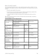
PMP 450 Platform Family modules provide the VLAN frame filters that are described in VLAN filters in
point-to-multipoint modules.
Table 112 :VLAN filters in point-to-multipoint modules
Where VLAN is active,
if this parameter value
is selected …
then a frame is discarded if…
because of this VLAN filter
in the software:
entering the bridge/
NAT switch through…
Ethernet…
TCP/IP…
any combination of
VLAN
parameter settings
with a VID not in the
membership table
Ingress
any combination of
VLAN
parameter settings
with a VID
not in the
membership
table
Local Ingress
Allow
Frame
Types:
Tagged Frames Only
with no 802.1Q tag
Only Tagged
Allow Frame Types:
Untagged Frames
Only
with an 802.1Q tag,
regardless of VID
Only Untagged
Local SM Management:
Disable in the SM, or
All Local SM
Management:
Disable in the AP
with an 802.1Q tag and a VID in the
membership table
Local SM Management
leaving the bridge/
NAT switch through…
Ethernet
TCP/IP
any combination of
VLAN
parameter settings
with a VID not in the
membership table
Egress
Содержание PMP 450 Series
Страница 92: ...Chapter 2 System hardware 92 Figure 29 MicroPoP Omni antenna implementation pattern Vertical...
Страница 134: ...Chapter 3 System planning 134 Figure 51 Mast or tower installation...
Страница 135: ...Chapter 3 System planning 135 Figure 52 Wall installation...
Страница 136: ...Chapter 3 System planning 136 Figure 53 Roof installation...
Страница 137: ...Chapter 3 System planning 137 Figure 54 GPS receiver wall installation...
Страница 158: ...Chapter 3 System planning 158 Figure 61 cnMedusa Antenna...
Страница 258: ...Chapter 5 Installation 258 Figure 123 Yagi antenna alignment horizontally Figure 124 Yagi antenna alignment upward tilt...


