Chapter 3: System planning
185
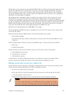
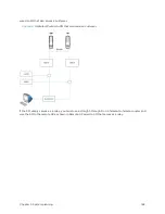
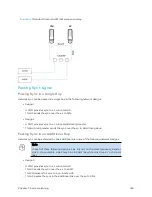
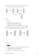
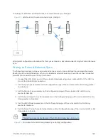
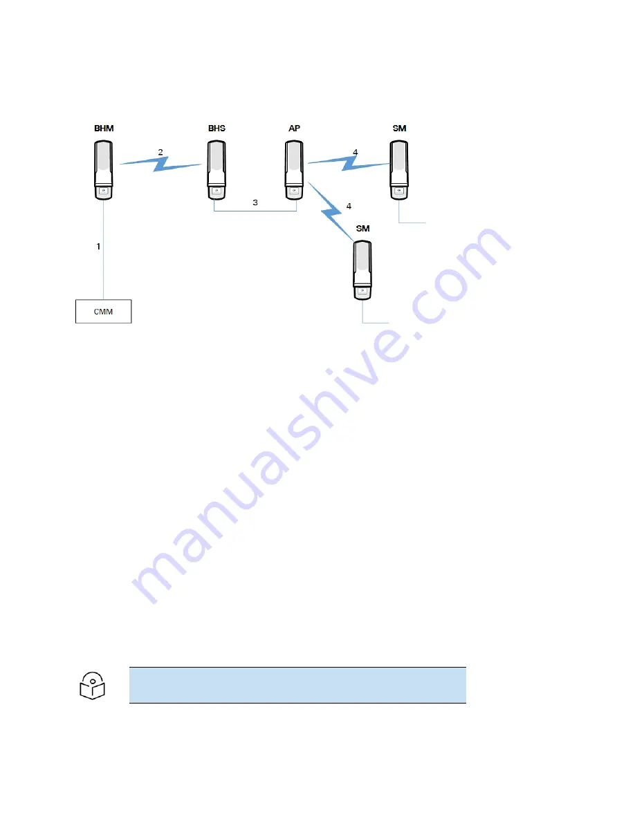
This design is illustrated in Additional link to extend network sync, Design 5.
Figure 72 :
Additional link to extend network sync, Design 5
Wiring and configuration information for this sync extension is described under Wiring to Extend Network
Sync.
W ir ing t o Ext end Net w or k Sync
The following procedure can be used to extend network sync by one additional hop, as described under
Passing Sync in an Additional Hop. When a co-located module receives sync over the air, the co-located
modules can be wired to pass the sync as follows:
1. Connect the GPS Utility ports of the co-located modules using a sync cable with RJ-11 (for 450) or
RJ-45 (for 450i/450m) connectors.
2. Set the Sync Input parameter on the Configuration page of the co-located AP or BH timing master
to AutoSync.
3. Set the Device Type parameter on the Configuration page of the co-located AP or BH timing
master to Remote.
4. Set the Sync Output to Aux Port parameter on the Configuration page of the co-located AP or BH
timing master to Disabled.
5. Set the UGPS Power parameter on the Configuration page of the co-located AP or BH timing
master to Disabled.
6. Set the Frame Timing Pulse Gated parameter on the Configuration page of the co-located SM or BH
timing slave to Enable.
Note
This setting prevents interference if the SM or BH timing slave loses sync.
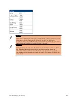
Figure 73 :
Co-located AP or BH timing master Sync Setting configuration
Содержание PMP 450 Series
Страница 92: ...Chapter 2 System hardware 92 Figure 29 MicroPoP Omni antenna implementation pattern Vertical...
Страница 134: ...Chapter 3 System planning 134 Figure 51 Mast or tower installation...
Страница 135: ...Chapter 3 System planning 135 Figure 52 Wall installation...
Страница 136: ...Chapter 3 System planning 136 Figure 53 Roof installation...
Страница 137: ...Chapter 3 System planning 137 Figure 54 GPS receiver wall installation...
Страница 158: ...Chapter 3 System planning 158 Figure 61 cnMedusa Antenna...
Страница 258: ...Chapter 5 Installation 258 Figure 123 Yagi antenna alignment horizontally Figure 124 Yagi antenna alignment upward tilt...

