Chapter 5: Installation
270
Note
For instructions on CMM3 (CMMmicro) or CMM4 installation, including the outdoor
temperature range in which it is acceptable to install the unit, tools required, mounting and
cabling instructions, and connectivity verification, please see the PMP Synchronization
Solutions User Guide located on the Cambium website.
Inst alling CMM4
The Cluster Management Module 4 (CMM4) provides power, sync, and network connectivity for up to
eight APs, backhauls, and Ethernet terrestrial feeds in a variety of configurations.
The CMM4 provides:
l
Sync over Power over Ethernet and integrated surge suppression on the controller board for up to
8 APs or BHs. Both a custom 30 VDC power scheme and a custom 56 VDC power scheme are
available. Neither is the same as the later IEEE Standard 802.3af, and neither is compatible with it.
l
Managed switching using a hardened EtherWAN switch (1090CKHH models). The CMM4 ships with
a 14-port EtherWAN switch and is also available without a switch. The CMM4 originally shipped with
a 9-port EtherWAN switch.
l
Surge suppression on the controller board for the incoming 30V DC and 56V DC power lines and
GPS coax cable.
l
Auto-negotiation on the Ethernet ports. Ports will auto-negotiate to match inputs that are either
100Base-T or 10Base-T, and either full duplex or half duplex, when the connected device is set to
auto-negotiate. Alternatively, these parameters are settable.
l
An always-on NTP (Network Time Protocol) server that can provide date and time to any radio that
can reach the CMM’s management IP address.
l
CNUT can be used to upgrade the CMM-4 software.
450 Series and 450i Series can use the CMM4’s EtherWan switch for their network connectivity.
Sup p lem ent al inst allat io n inf o rm at io n
This section contains detailed installation procedures that are not included in the above topics, such as
how to strip cables, create grounding points and weatherproof connectors.
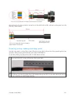
St r ip p ing d r op cab le
When preparing the drop cable for connection to the 450 Platform Family ODU or LPU, use the following
measurements:
Содержание PMP 450 Series
Страница 92: ...Chapter 2 System hardware 92 Figure 29 MicroPoP Omni antenna implementation pattern Vertical...
Страница 134: ...Chapter 3 System planning 134 Figure 51 Mast or tower installation...
Страница 135: ...Chapter 3 System planning 135 Figure 52 Wall installation...
Страница 136: ...Chapter 3 System planning 136 Figure 53 Roof installation...
Страница 137: ...Chapter 3 System planning 137 Figure 54 GPS receiver wall installation...
Страница 158: ...Chapter 3 System planning 158 Figure 61 cnMedusa Antenna...
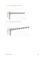
Страница 258: ...Chapter 5 Installation 258 Figure 123 Yagi antenna alignment horizontally Figure 124 Yagi antenna alignment upward tilt...

