Chapter 4: Preparing for installation
199
2
Select Tools, Internet Options, Connections, LAN Settings. Alternate web browser menu selections
may differ.
3 Uncheck the Use a proxy server box.
In the address bar of your browser, enter the IP address of the AP/BHM. (For example, enter
http://169.254.1.1 to access the AP/BHM through its default IP address). The AP/BHM responds by opening
the General Status tab of its Home page.
Log g ing int o t he w eb int er f ace – A P/ SM/ BH
Procedure 4 Logging into the web interface
1
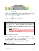
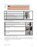
Plug one end of a CAT 5 Ethernet cable into the AP/BHM
2
Plug the Ethernet cable connector labeled To Radio into the jack in the pig tail that hangs from the
power supply.
3
Plug the other connector of the pig tail (this connector labeled To Computer) into the Ethernet jack
of the computing device.
4
Plug the power supply into an electrical outlet.
Warning
From this point until you remove power from the ODU, stay at least as far from the ODU
as the minimum separation distance specified.
Using t he Quick St ar t Conf ig ur at ion W izar d of t he A P/ BHM
See section Quick Link Setup section in Configuration Guide.
Содержание PMP 450 Series
Страница 92: ...Chapter 2 System hardware 92 Figure 29 MicroPoP Omni antenna implementation pattern Vertical...
Страница 134: ...Chapter 3 System planning 134 Figure 51 Mast or tower installation...
Страница 135: ...Chapter 3 System planning 135 Figure 52 Wall installation...
Страница 136: ...Chapter 3 System planning 136 Figure 53 Roof installation...
Страница 137: ...Chapter 3 System planning 137 Figure 54 GPS receiver wall installation...
Страница 158: ...Chapter 3 System planning 158 Figure 61 cnMedusa Antenna...
Страница 258: ...Chapter 5 Installation 258 Figure 123 Yagi antenna alignment horizontally Figure 124 Yagi antenna alignment upward tilt...

