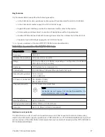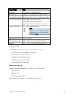
About This User Guide
14
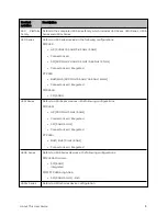
Product
notation
Description
PMP 450m
l
AP 5 GHz
o
Integrated
l
AP 3 GHz
o
Integrated
450 MicroPoP
Series
Refers to 450 MicroPoP Series devices in the following configurations:
l
PMP 450 MicroPop Omni 5 GHz Integrated
l
PMP 450 MicroPop Sector 5 GHz Integrated
450b Retro
Series
Refers to 450b Retro Series devices in the following configurations:
l
PMP 450b Retro SM 5 GHz integrated
Cr oss r ef er ences
References to external publications are shown in italics. Other cross references, emphasized in blue text in
electronic versions, are active links to the references.
This document is divided into numbered chapters that are divided into sections. Sections are not
numbered but are individually named at the top of each page and are listed in the table of contents.
Feed b ack
We appreciate feedback from the users of our documents. This includes feedback on the structure,
content, accuracy, or completeness of our documents. To provide feedback, visit our support
website.
https://support.cambiumnetworks.com
.
Caution
This device complies with Part 15 of the FCC Rules. Operation is subject to the
following two conditions:
l
This device may not cause harmful interference, and
l
This device must accept any interference received, including interference
that may cause undesired operation
Im p o rt ant reg ulat o ry inf o rm at io n
The 450 Platform Family products are certified as an unlicensed device in frequency bands where it is not
allowed to cause interference to licensed services (called primary users of the bands).
Содержание PMP 450 Series
Страница 92: ...Chapter 2 System hardware 92 Figure 29 MicroPoP Omni antenna implementation pattern Vertical...
Страница 134: ...Chapter 3 System planning 134 Figure 51 Mast or tower installation...
Страница 135: ...Chapter 3 System planning 135 Figure 52 Wall installation...
Страница 136: ...Chapter 3 System planning 136 Figure 53 Roof installation...
Страница 137: ...Chapter 3 System planning 137 Figure 54 GPS receiver wall installation...
Страница 158: ...Chapter 3 System planning 158 Figure 61 cnMedusa Antenna...
Страница 258: ...Chapter 5 Installation 258 Figure 123 Yagi antenna alignment horizontally Figure 124 Yagi antenna alignment upward tilt...


