Chapter 5: Installation
225
1
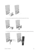
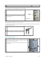
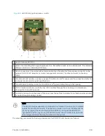
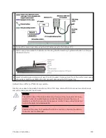
Remove the cover of the 600SSH Surge Suppressor.
2
With the cable openings facing downward, mount the 600SSH to the outside of the subscriber
premises, as close to the point where the Ethernet cable penetrates the residence or building as
possible, and as close to the grounding system (Protective Earth) as possible.
3
Wrap an AWG 10 (or 6mm
2
) copper wire around the Ground post of the 600SSH.
4
Tighten the Ground post locking nut in the 600SSH onto the copper wire.
5
Securely connect the copper wire to the grounding system (Protective Earth) according to
applicable regulations.
6
Using diagonal cutters or long nose pliers, remove the knockouts that cover the cable openings to
the 600SSH.
7
Pack both surge suppressor Ethernet jacks with dielectric grease.
8
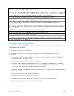
Wrap a splice loop in the loose end of the Ethernet cable from the SM.
9
Connect that cable to one of the Ethernet jacks.
10
Connect an Ethernet cable to the other Ethernet jack of the 600SSH and to the power adapter.
11
Replace the cover of the 600SSH.
Gener al p r ot ect ion inst allat ion
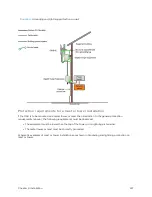
To adequately protect a 450 Platform Family installation, both ground bonding and transient voltage
surge suppression are required.
Grounding cable requirement s
When routing, fastening and connecting grounding cables, the following requirements must be
implemented:
l
Grounding conductors must be run as short, straight, and smoothly as possible, with the fewest
possible number of bends and curves.
l
Grounding cables must not be installed with drip loops.
l
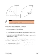
All bends must have a minimum radius of 203 mm (8 in) and a minimum angle of 90° (Grounding
cable minimum bend radius and angle). A diagonal run is preferable to a bend, even though it does
not follow the contour or run parallel to the supporting structure.
l
All bends, curves and connections must be routed towards the grounding electrode system, ground
rod, or ground bar.
l
Grounding conductors must be securely fastened.
l
Braided grounding conductors must not be used.
l
Approved bonding techniques must be used for the connection of dissimilar metals.
Figure 83 :
Grounding cable minimum bend radius and angle
Содержание PMP 450 Series
Страница 92: ...Chapter 2 System hardware 92 Figure 29 MicroPoP Omni antenna implementation pattern Vertical...
Страница 134: ...Chapter 3 System planning 134 Figure 51 Mast or tower installation...
Страница 135: ...Chapter 3 System planning 135 Figure 52 Wall installation...
Страница 136: ...Chapter 3 System planning 136 Figure 53 Roof installation...
Страница 137: ...Chapter 3 System planning 137 Figure 54 GPS receiver wall installation...
Страница 158: ...Chapter 3 System planning 158 Figure 61 cnMedusa Antenna...
Страница 258: ...Chapter 5 Installation 258 Figure 123 Yagi antenna alignment horizontally Figure 124 Yagi antenna alignment upward tilt...

