Chapter 2: System hardware
108
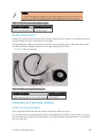
l
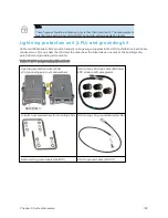
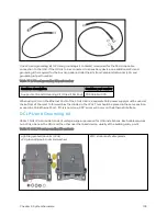
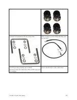
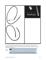
Cable grounding kits: Order one cable grounding kit for each grounding point on the antenna
cables. Refer to Ethernet cable testing .
l
Self-amalgamating and PVC tape: Order these items to weatherproof the RF connectors
l
Lightning arrestors: When the connectorized ODU is mounted indoors, lightning arrestors (not
LPUs) are required for protecting the antenna RF cables at building entry. One arrestor is required
per antenna cable. One example of a compatible lightning arrestor is the Polyphaser LSXL-ME or
LSXL (not supplied by Cambium Networks).
GPS sy nchro nizat io n
GPS synchr onizat ion d escr ip t ion
Cambium offers GPS synchronization to limit the network’s own self-interference. The Cluster Management
CMM provides Global Positioning System (GPS) synchronization to the Access Point (AP) and all
associated Subscriber Modules (SM). Network operators have a choice of UGPS and CMM solutions to
select the option that works best for the environment.
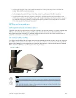
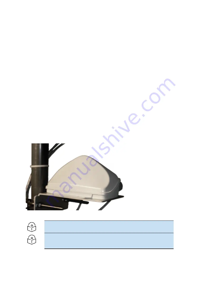
Univer sal GPS ( UGPS)
The UGPS provides network synchronization for smaller networks where a CMM may not be cost effective.
The UGPS provides synchronization for one or two modules so that even remote areas at the edge of the
network can operate with synchronization for improved performance. The UGPS works with all Cambium
PMP radios. The UGPS has a small footprint and is easy to deploy.
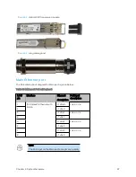
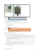
Figure 39 :
UGPS
Note
PMP 450/450i/450m Series - APs can power up a UGPS via the Aux/Timing port.
Note
PMP 450i/450b/450m Series - If two units are to get sync from the UGPS, then
an external power supply is required.
Содержание PMP 450 Series
Страница 92: ...Chapter 2 System hardware 92 Figure 29 MicroPoP Omni antenna implementation pattern Vertical...
Страница 134: ...Chapter 3 System planning 134 Figure 51 Mast or tower installation...
Страница 135: ...Chapter 3 System planning 135 Figure 52 Wall installation...
Страница 136: ...Chapter 3 System planning 136 Figure 53 Roof installation...
Страница 137: ...Chapter 3 System planning 137 Figure 54 GPS receiver wall installation...
Страница 158: ...Chapter 3 System planning 158 Figure 61 cnMedusa Antenna...
Страница 258: ...Chapter 5 Installation 258 Figure 123 Yagi antenna alignment horizontally Figure 124 Yagi antenna alignment upward tilt...

