


Learning Advanced Features
110
890054-00-00
GM2 Series VFD
Code and
Features
Description
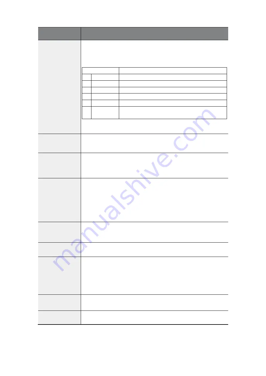
AP.20 PID Ref
Source
Selects the reference source for PID control. The reference and
feedback (AP.21) cannot be the same source. If V1 is set as the
feedback source, V1 cannot be the reference source. To set V1 as a
reference source (AP.20), change the feedback source (AP.21).
Configuration
Function
0
Keypad
Keypad
1
V1
-10
–
10 V input voltage terminal
3
V0
Potentiometer (Volume dial) input on keypad
4
I2
I2 4
–
20 mA input voltage terminal
5
Int. 485
RS-485 input terminal
7
FieldBus
Communication command via a communication
option card
When using the keypad, the PID reference setting is entered in AP.19.
The reference setting can be displayed at AP.17.
AP.21 PID F/B
Source
Selects feedback source for PID control. The same items as AP.20 can
be selected as the feedback source, except the keypad. Feedback
cannot be set to the same as the reference (AP.20).
AP.22 PID P-Gain,
AP.26 P Gain Scale
Sets the output ratio for differences (errors) between reference and
feedback. If the P-gain is set to 50%, then 50% of the error is output.
The setting range for P-gain is 0.0-1,000.0%. For ratios below 0.1%,
use AP.26 (P Gain Scale).
AP.23 PID I- Time
Sets the time to output accumulated errors. When the error is 100%,
the time taken for 100% output is set. When the integral time (PID I-
Time) is set to 1 second, 100% output occurs after 1 second of the
error remaining at 100%. Differences in a normal state can be
reduced by PID I Time. When the multi-function (digital) terminal
block is set to 21 (I-Term Clear) and is activated, all of the
accumulated errors are deleted.
AP.24 PID D-Time
Sets the output volume for the rate of change in errors. If the
differential time (PID D-Time) is set to 1 ms and the rate of change in
errors per sec is 100%, output occurs at 1% per 10 ms.
AP.25 PID F-Gain
Feed Forward Gain - Sets the ratio that adds the target to the PID
output. Adjusting this value leads to a faster response.
AP.27 PID Out LPF
Used when the output of the PID controller changes too fast or the
entire system is unstable, due to severe oscillation. In general, a lower
value (default value=0) is used to speed up response time, but in
some cases a higher value increases stability. The higher the value,
the more stable the PID controller output is, but the slower the
response time.
AP.29 PID Limit Hi,
AP.30 PID Limit Lo
Apply limits to the output of the controller.
AP.32 PID Out
Scale
Adjusts the volume of the controller output.
Содержание RSi GM2 Series
Страница 2: ...ii...
Страница 58: ...48 GM2 Series VFD Perform Basic Operations 890054 00 00...
Страница 122: ...Learning Advanced Features 112 890054 00 00 GM2 Series VFD PID control block diagram...
Страница 188: ...Learning Protection Features 178 GM2 Series VFD 890054 00 00...
Страница 279: ...Technical Specification 269 890054 00 00 GM2 Series VFD...


