28
Installation
Frame Interface
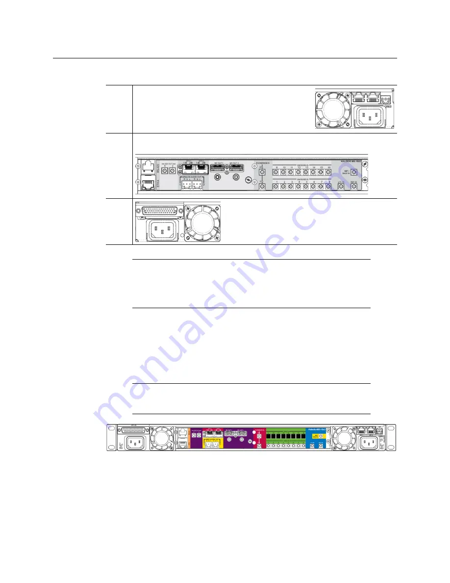
Viewed from the back of the frame, the three sections are laid out as follows:
Kaleido-MX 8 × 1, and 8 × 2
Kaleido-MX systems with
8 inputs
are available in single-head and dual-head models. They
share the same rear-panel layout, including 8 input connectors, 2 HDMI outputs, 2 HD-SDI
monitoring outputs, 2 analog audio outputs, 1 ABT/MADI audio input, 1 LTC input,
1 reference input, 1 Ethernet connector, 1 RS-422 connector, 20 GPI inputs, and
8 configurable GPI input/output.
Kaleido-MX-8x2 rear panel (same panel as Kaleido-MX-16x2)
Kaleido-MX 16 × 1, 16 × 2, and 16 × 4
Kaleido-MX systems with
16 inputs
are available in single-head, dual-head, and quad-head
models.
• The single-head and dual-head models share the same rear-panel layout, including
16 input connectors, 2 HDMI outputs (one of which is not enabled, in the case of the
Right
This area contains inputs and outputs for the
controller
card: the fan speed control setting switch, a GPI port and
two Ethernet ports. It also contains the power socket for
the power supply located beneath the controller card,
and one of the two frame fans.
Center This area contains the connectors associated with your multiviewer’s input and
output cards.
Left
This area contains the power socket for the power
supply located beneath the GPI-1501 card, and one of
the two frame fans.
Note:
The Kaleido-MX (1RU) offers a wide variety of ports for incoming and
outgoing signals. With a view towards future expansion, there are ports
whose connections exist but that are currently not fully supported. The
FlexBridge IN
ports are reserved for future expansion, and the
SFP
ports are
not yet supported.
Note:
In the case of the HDMI outputs, HD-SDI monitoring outputs, and
analog audio outputs, in each pair, the output associated with the second
head is NOT enabled if your Kaleido-MX is a single-head model.


