32
Installation
Card Interfaces
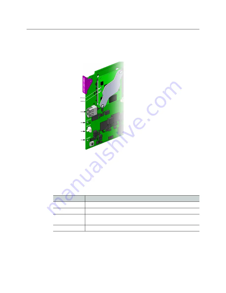
KMX-3901-OUT Front Card-edge Description
Every output module also has one USB connector, into which you may connect a mouse,
keyboard, or USB flash memory for a software upgrade or data backup. The diagram below
shows the USB connector, between various LED indicators and the Select button, on the
output cards’ front edge.
Summary view of the interface on a Kaleido-MX output card edge
Output card Status LED
Once the startup has completed, the status LEDs on the
output cards
should be red (steady)
because the cards are not connected to the network yet.
The Status LED is located on the front edge of a Kaleido-MX card, immediately above the
Select button, and is visible through the front access door of the Densité frame. This multi-
color LED indicates the status of the card, by color, and by flashing/steady illumination:
The Status LED always shows the most severe detected error status. In the table above,
error severity increases from top to bottom, with green representing no error/disabled, and
flashing red the most severe error conditions.
If the Status LED is flashing orange, it means that the card is selected for local control using
the Densité frame’s control panel (or that the card is booting up). See
, on page 48 for details.
Status LED Color
Meaning
Green
Normal
Flashing orange
Booting (or the card is selected for local control)
Red
Firmware initialization in progress / no Ethernet / SD card error / CPU
kernel error / update in progress (may last up to 10 minutes)
Flashing red
Fan failure / no rear / duplicate IP address
Status LED
Select button
Power LED
Output card front
edge (bottom)
USB connector
Heartbeat LED
SD card access LED
Top side:
ETH com LED
(future use)
CPU 0 LED
(not used)
CPU 1 LED


