Instructions for Use
3 Description of the device
OPMI LUMERA 700
3.2 Device setup
G-30-1673-en - 14.0 - 2018-07-12
49 / 236
5
YPbPr video output
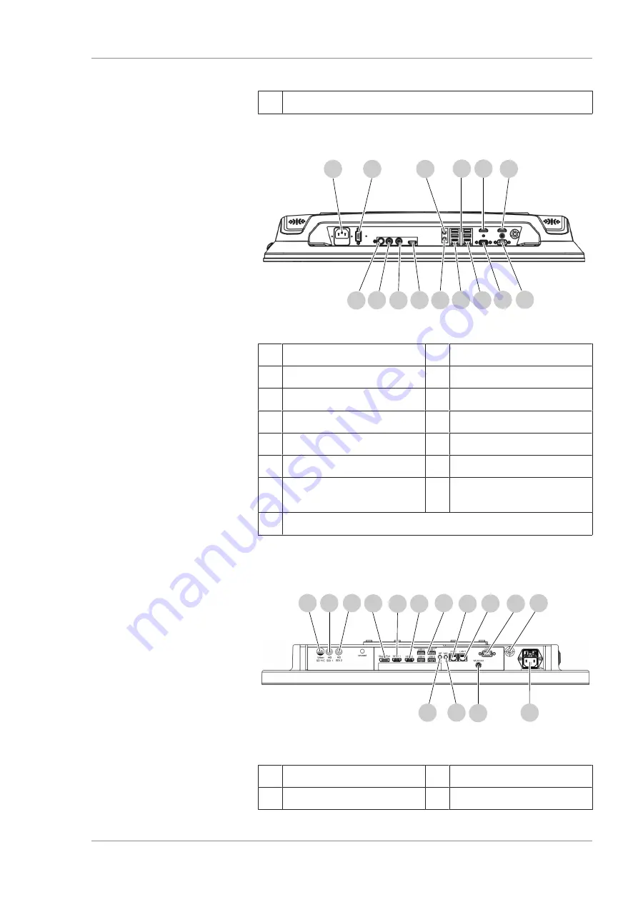
3.2.21 CALLISTO eye Panel PC connector panel (model I)
7
8
9
10
11
12
13
14
1
2
3
4
5
6
15
Figure 26: CALLISTO eye Panel PC connector panel (model I)
1
Voltage connection
2
COM port
3
Microphone port
4
USB ports (4x)
5
HDMI port (disabled)
6
HDMI port for IDIS
7
COM port (disabled)
8
VGA port (disabled)
9
Network connection
10
Network connection
11
Speaker port
12
HDMI port (disabled)
13
HD-SDI video output
(disabled)
14
HD-SDI video input
15
Y/C video input
3.2.22 CALLISTO eye Panel PC connector panel (model II)
4
9
12
5
7
8
10
1
2
3
6
11
13
14
15
Figure 27: CALLISTO eye Panel PC connector panel (model II)
1
Y/C video input
2
HD-SDI 1 video input
3
HD-SDI 2 (disabled)
4
Display port
Summary of Contents for opmi lumera 700
Page 1: ...OPMI LUMERA 700 Software Release 3 1 Instructions for Use...
Page 10: ...Empty page for your notes...
Page 14: ...Empty page for your notes...
Page 30: ...Empty page for your notes...
Page 130: ...Empty page for your notes...
Page 200: ...Empty page for your notes...
Page 222: ...Empty page for your notes...
Page 226: ...Empty page for your notes...
Page 230: ...Empty page for your notes...
Page 235: ...Empty page for your notes...


