


118
CHAPTER FOUR
crank wheels, the crankshaft must be disas-
sembled. Refer service to a qualified dealer-
ship or crankshaft specialist.
NOTE
Do not check crankshaft
with the
crankshaft placed between lathe centers.
Use V-blocks as described in Step
9.
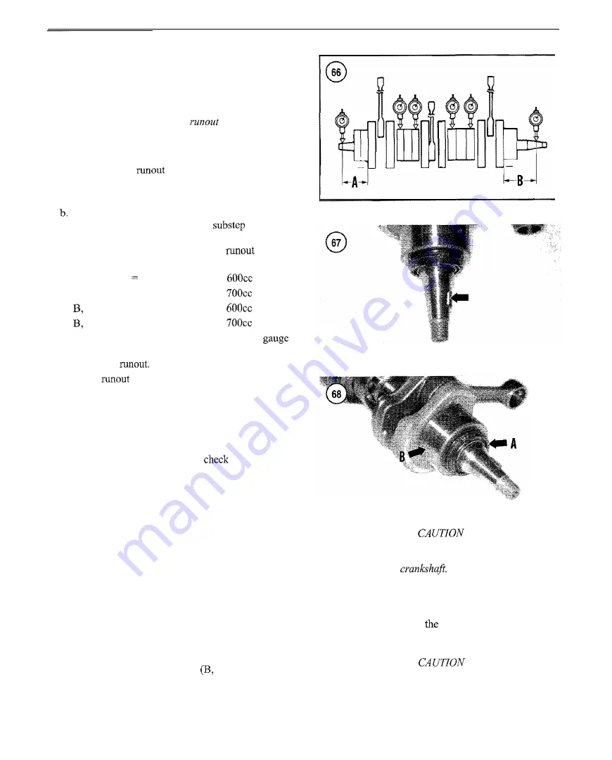
9. Check crankshaft
as follows:
a. Support the crankshaft by placing the main bearings
at the ends onto two precision V-blocks.
Position the dial indicators at locations
A
and
B in-
dicated in Figure 66. Refer to
c for the
proper placement of the dial indicator plunger in re-
lation to the crank web. Refer to the
specifi-
cations in Table
2
and Table 3.
c. A, Figure 66 80 mm (3.15 in.) on
models.
A,
Figure
66
=
90 mm (3.54 in.) on
models.
Figure
66
=
99
mm (3.90 in.) on
models.
Figure
66
=
85
mm
(3.35 in.) on
models.
d. Turn the crankshaft slowly and observe the
reading. The maximum difference recorded is
crankshaft
e. If the
at any position exceeds the service
limit (Table 2 or Table 3), have the crankshaft ser-
viced by a dealership or crankshaft specialist.
10. Check the crankshaft threads for stripping,
cross-threading or other damage. Have threads repaired
by a dealership or machine shop.
11.
Remove the key (Figure 67) and
the keyway in
the crankshaft for cracks or other damage.
If the keyway is
damaged, refer service to a dealership or machine shop.
12. If the crankshaft exceeded any of the service limits or
if one or more bearings are worn or damaged, have the
crankshaft rebuilt by a dealership or crankshaft specialist.
Crankshaft Bearing Replacement
Replace the outer crankshaft bearings and outer seals as
follows.
1. Remove the seal
(A,
Figure
68) from the flywheel end
of the crankshaft.
2. Clean the crankshaft bearing area with solvent or elec-
trical contact cleaner and thoroughly
dry.
3. Remove the roller type bearing
Figure
68) from
the flywheel end of the crankshaft.
4.
Remove the ball type main bearings from the PTO end
of the crankshaft as follows.
The procedure necessary to move the bear-
ing far enough to install the puller may
damage the
a. Support the crankshaft and use a chisel (Figure 69,
typical) or bearing splitter to move the outer bearing
toward the end of
crankshaft far enough to in-
stall a bearing puller.
When using a puller to remove bearings
from
the end of the crankshaft, place a pro-
tective cap over the end of the crankshaft to
prevent the puller screw from damaging it.
Summary of Contents for MM700A
Page 5: ......
Page 6: ......
Page 104: ...98 CHAPTER FOUR ENGINE MOUNTS...
Page 137: ...FUEL AND EXHAUSTSYSTEMS 131...
Page 144: ...138 CHAPTER FIVE CARBURETOR HEATER SYSTEM Carburetorheater control valve...
Page 211: ...BRAKES 205 Wear limit...
Page 226: ...220 CHAPTER TWELVE...
Page 228: ...222 CHAPTER TWELVE...
Page 229: ...CHAINCASE JACKSHAFTAND FRONT AXLE 223...
Page 230: ...224 CHAPTER TWELVE...
Page 254: ...248 CHAPTER THIRTEEN FORWARD Negative Positive O0Camber Angle finder...
Page 277: ...1 Wiring Diagrams...
Page 282: ...NOTES...