


E
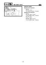
CRANKSHAFT AND CYLINDER BODY
POWR
CRANKSHAFT AND CYLINDER BODY
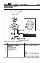
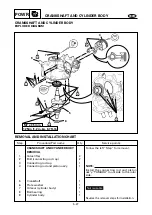
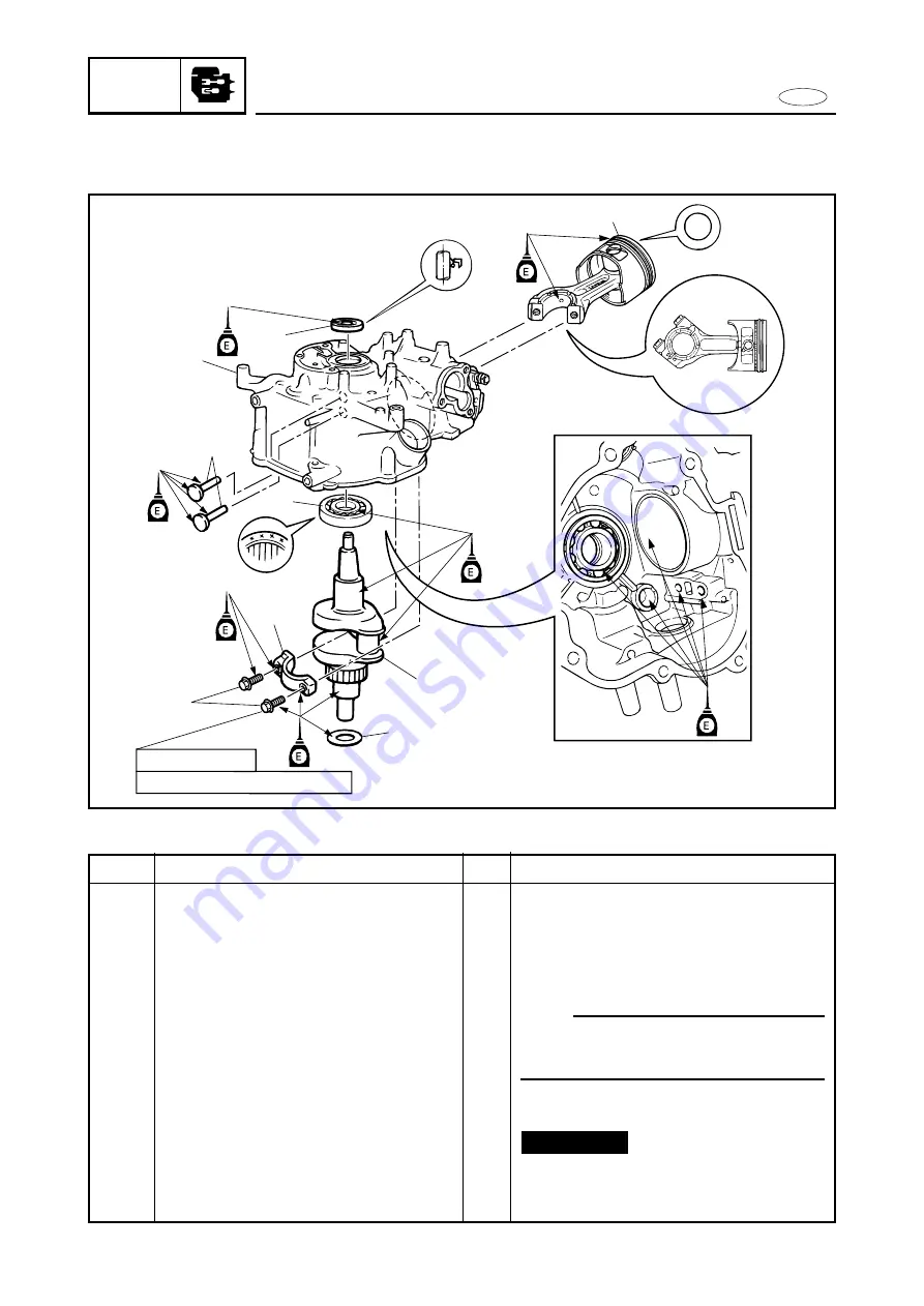
EXPLODED DIAGRAM
5
9
2
1
8
7
12 Nm (1.2 m•kg, 8.7 ft•lb)
3
6
M7 x 35 mm
4
UP
5-27
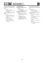
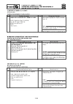
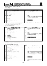
REMOVAL AND INSTALLATION CHART
Step
1
2
3
4
5
6
7
8
9
Q’ty
2
2
1
1
1
1
1
1
1
Service points
Follow the left “Step” for removal.
NOTE:
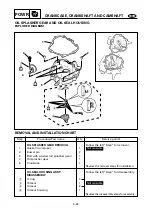
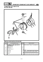
Install the connecting rod and piston
ass’y “YAMAHA” mark side to the rotor
side.
Reverse the removal steps for installation.
Not reusable
Procedure/Part name
CRANKSHAFT AND CYLINDER BODY
REMOVAL
Valve lifter
Bolt (connecting rod cap)
Connecting rod cap
Connecting rod and piston ass’y
Crankshaft
Plate washer
Oil seal (cylinder body)
Ball bearing
Cylinder body